
AC Motor Speed Control circuit

This AC motor speed controller is designed to regulate the speed of brushed AC motors and other compatible loads, up to a maximum power rating of 250W. Its operation is similar to that of a light dimmer, utilizing phase-cutting techniques to adjust the effective voltage supplied to the load. This makes it suitable for various applications, including incandescent lighting and heating elements, in addition to electric motors.
The circuit architecture comprises several key components: resistors, capacitors, a TRIAC, a DIAC opto-isolator, and a bridge rectifier, among others. The resistors (R1 to R13) serve multiple purposes, including setting the biasing levels for the transistor and TRIAC, adjusting the feedback loop for voltage regulation, and providing fine-tuning capabilities for motor speed control. Notably, R9 allows for adjustment of the motor speed, while R10 and R8 are trim pots for calibrating the circuit's feedback and gate voltage, respectively.
Capacitors C1, C2, and C3 play critical roles in filtering and stabilizing the circuit. C2, an electrolytic capacitor rated at 100 µF, helps smooth out voltage fluctuations, while C1 and C3, ceramic disc capacitors rated at 0.1 µF, are used for high-frequency noise suppression.
The circuit is equipped with a 6V Zener diode (D1) to provide voltage regulation, ensuring that the control circuitry operates reliably. The NPN transistor (Q1), such as the 2N2222 or 2N3904, acts as a switch to control the TRIAC (SCR1), which is responsible for handling the high power delivered to the load.
The TRIAC must be selected based on the load's requirements, and a compatible DIAC opto-isolator (U1) is used to ensure safe isolation between the control and power circuits. The circuit also includes a transformer (T1) with a recommended turns ratio of 1:10 to step down the voltage for the control circuitry.
For assembly, it is imperative that the circuit is housed within an insulated case to prevent accidental contact with mains voltage, as the design does not isolate the control circuitry from the AC power source. The inclusion of heatsinks is also advised to dissipate heat generated by the TRIAC during operation, particularly under high load conditions.
In summary, this AC motor speed controller is a versatile solution for controlling the speed of brushed AC motors and other resistive loads, providing effective voltage regulation through a well-designed circuit configuration.This AC motor speed controller can handle most universal type (brushed) AC motors and other loads up to about 250W. It works in much the same was a light dimmer circuit; by chopping part of the AC waveform off to effectively control voltage.
Because of this functionality, the circuit will work for a wide variety of loads including incandescent light bulbs, heating elements, brushed AC motors and some transformers. The circuit tries to maintain a constant motor speed regardless of load so it is also ideal for power tools.
Note that the circuit can only control brushed AC motors. Inductive motors require a variable frequency control. R1 1 27K 1W Resistor R2 1 10K 1/4W Resistor R3 1 100K 1/4W Resistor R4 1 33K 1/4W Resistor R5 1 2.2K 1/4W Resistor R6 1 1K 1/4W Resistor R7 1 60K Ohm 1/4W Resistor R8 1 3K Linear Taper Trim Pot R9 1 5K Linear Taper Pot R10 1 4.7K Linear Taper Trim Pot R11 1 3.3K 1/4W Resistor R12 1 100 Ohm 1/4W Resistor R13 1 47 Ohm 1W Resistor (See Notes) C1, C3 2 0.1uF Ceramic Disc Capacitor C2 1 100uF 50V Electrolytic Capacitor D1 1 6V Zener Diode Q1 1 2N2222 NPN Transistor 2N3904 SCR1 1 ECG5400 TR1 1 TRIAC (See Notes) U1 1 DIAC Opto-Isolator (See Notes) BR1, BR2 2 5A 50V Bridge Rectifier T1 1 Transformer (See Notes) MISC 1 PC Board, Case, Line Cord, Socket For U1, Heatsinks Notes TR1 must be chosen to match the requirements of the load. Most generic TRIACs with ratings to support your load will work fine in this circuit. If you find a TRIAC that works well, feel free to leave a comment. U1 must be chosen to match the ratings of TR1. Most generic DIAC based opto-isolators will work fine. If you have success with a specific part, feel free to leave a comment. T1 is any small transformer with a 1:10 turns ratio. The circuit is designed to run on 120V so a 120V to 12V transformer will work. Alternately, you can wind T1 on a transformer core using a primary of 25 turns, a secondary of 200 turns, and 26 gauge magnet wire.
R9 is used to adjust motor speed. R10 is a trim pot used to fine tune the governing action of the circuit. R8 fine tunes the feedback circuit to adjust for proper voltage at the gate of SCR1. It should be adjusted to just past the minimum point at which the circuit begins to operate. R13 must be chosen to match the load. Generally, larger loads will require a smaller value. Since this circuit is not isolated from mains, it must be built in an insulated case. 🔗 External reference
Related Circuits
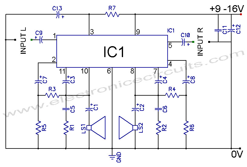
TDA2004 Car Battery 12W Stereo Amplifier Circuit. Its main features are low distortion, low noise, and high reliability of the chip. The TDA2004 is a highly integrated audio amplifier designed specifically for automotive applications. This circuit is capable of delivering...
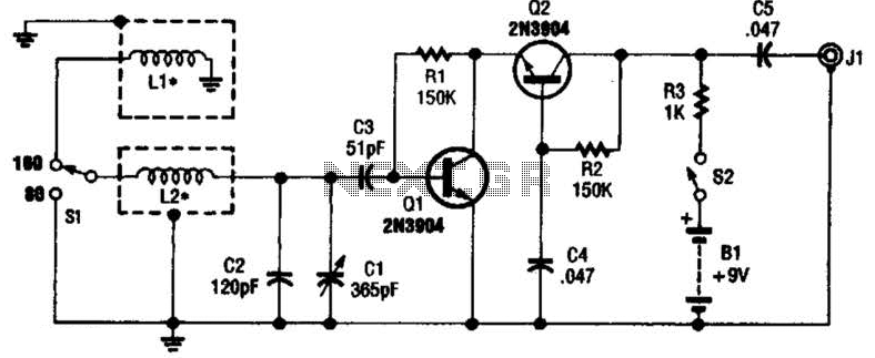
This antenna may assist in minimizing power-line noise. It consists of a plastic hula hoop or conduit with a diameter of 3 feet, which is covered with aluminum foil to serve as a shield for LI and L2. LI...
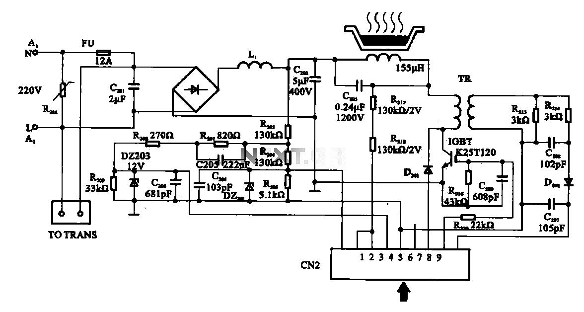
Cooker detection control circuit. The control circuit is designed for testing cookers. The inductance coil disc lesion typically measures around 150 µH. The stove plate coil and capacitor resonate with device C203. When resonating, the voltage generated across C203...

The schematic closely resembles the one found in the CPLD Development Board Tutorial, as it is essentially the same board with a minor addition. The new components are located in the lower right corner, including eight DIP switches, a...
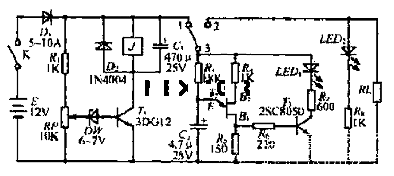
The discharge control circuit consists of a battery management system designed to prevent over-discharge of a battery. It features a relay control mechanism that activates when the battery voltage drops below a specified threshold of approximately 10.5V. The circuit...
This circuit is primarily designed as a timely reminder system for monitoring individuals on duty who may fall asleep. It features a detection circuit that processes minute signals. As the LED digital electronic timing clock displays the minute, the...