
Direct Coupled On/Off Touch Switch
The touch switch circuit employs a CA3240 dual BiMOS op-amp, which is known for its high input impedance and low offset voltage, making it ideal for sensing minute variations in current. The circuit operates by applying a small voltage to the touch plate, which is connected to one of the op-amp's inputs. When a finger touches the plate, it changes the capacitance and induces a small current that the op-amp can detect.
The configuration typically includes resistors and capacitors to set the sensitivity of the touch detection, allowing the circuit to respond to light touches while ignoring noise or unintentional contact. The output of the op-amp can be connected to a microcontroller or a transistor to control a load, such as an LED or a relay, based on the detected touch.
To enhance reliability, the circuit may incorporate hysteresis to prevent false triggering from noise or minor fluctuations in the signal. Additional features might include adjustable sensitivity through variable resistors, enabling the user to calibrate the touch response according to specific requirements.
Overall, this touch switch circuit design provides an efficient and effective method for implementing touch-sensitive controls in various applications, ranging from consumer electronics to industrial automation systems.The following touch switch circuit uses a CA3240 dual BiMOS op amp to sense small currents flowing between the contact points on a touch plate. Since this.. 🔗 External reference
Related Circuits
The modern mechanic switches are improved concerning old technology. We need, however, many times to replace some old switch or to check currents bigger than the durability of certain switches or simply we need something with a modern appearance....

This circuit is a touch switch circuit, similar to a touch door alarm. It utilizes a 555 timer as the core component of the touch switch circuit. The operation begins when the plate is touched, triggering the 555 timer....
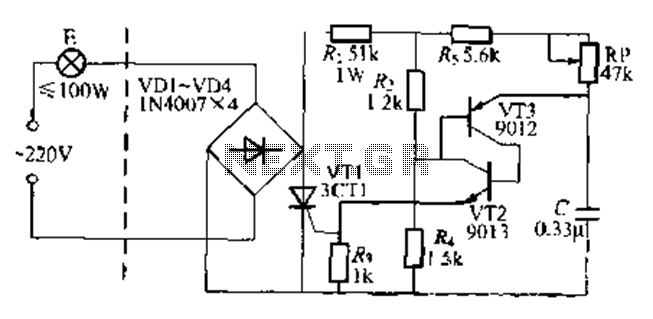
The circuit is a one-way ordinary transistor-triggered dimmer light circuit. It uses a complementary amplifier configuration with transistors VT2 and VT3 to form the thyristor trigger circuit for VT1. The circuit operates with a 220V alternating current through the...
By incorporating discrete inductors in series with the device, it is possible to "tune out" some of the capacitance and enhance the eye opening. By adding sufficient inductance to peak the third harmonic at 240 MHz, while considering the...
A relay-based on/off controller on the other hand can be very efficient. A typical relay has a contact resistance of 3 milliOhm. At 20A, this translates to a voltage drop of 0.06 volts, with a power loss of 1.2W....

A DC-coupled multi-stage amplifier circuit consists of multiple stages of amplification using a DC-coupled configuration. Each stage utilizes NPN-type transistors, which are designed to maintain appropriate operating points at the base of each stage. As the signal progresses through...
Warning: include(partials/cookie-banner.php): Failed to open stream: Permission denied in /var/www/html/nextgr/view-circuit.php on line 713
Warning: include(): Failed opening 'partials/cookie-banner.php' for inclusion (include_path='.:/usr/share/php') in /var/www/html/nextgr/view-circuit.php on line 713