
touch switch circuit using 555 ic

The touch switch circuit is designed around the versatile 555 timer IC, which is configured in a monostable mode to achieve the desired functionality. When a conductive object, such as a finger, makes contact with the touch plate, it causes a momentary change in voltage at the trigger pin (pin 2) of the 555 timer. This change triggers the timer, resulting in a high output at pin 3.
The LED and buzzer connected to this output serve as indicators, providing both visual and audible feedback. The specific duration for which the LED and buzzer remain active is governed by the time constant, which is determined by the resistor and capacitor values connected to pins 6 and 7. The time period (T) can be calculated using the formula:
T = 1.1 × R × C
where R is the resistance in ohms and C is the capacitance in farads. In this circuit, the presence of the 10 MΩ resistor at pin 2 ensures that the circuit responds effectively to even the slightest touch, enhancing its sensitivity. This characteristic makes the touch switch suitable for various applications, including security systems, home automation, and interactive displays.
The overall design of the circuit can be represented in a schematic, which includes the 555 timer, the touch plate, the LED, the buzzer, and the associated resistors and capacitors. Proper placement of these components is crucial for achieving optimal performance and reliability. Additionally, ensuring that the power supply is stable and within the specifications of the 555 timer is essential for the circuit’s functionality.This is a circuit for touch switch circuit. This circuit is almost same with touch door alarm. This circuit uses a 555 timer as the bases of the touch switch circuit. This is the figure of the circuit. The operation of this circuit is begin, when the plate is touched the 555 timer is triggered and the output on pin 3 goes high turning on the LED a nd the buzzer for a certain period of time. The time that the LED and the buzzer is on is based on the values of the capacitor and resistor connected to pin 6 & 7. The 10 M resistor is on pin 2 causes the circuit to be very sensitive to the touch. 🔗 External reference
Related Circuits
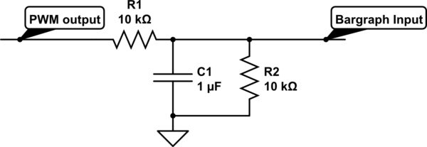
For a project, there is a need to display a progress bar representing the activity performed by a microcontroller unit (MCU). A bar graph display is intended for this purpose; however, the bar graph display driver IC, LM3914, requires...
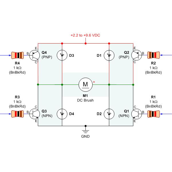
Selecting the appropriate DC motor is essential for constructing mobile robots. Testing DC motors is straightforward and can be accomplished by assembling a basic DC motor circuit. The components needed for this circuit include a DC motor, a battery...

The 3F155 circuit, as depicted in the provided figure, operates in manual control mode. It features a self-excitation braking phase, while the other two phases utilize a short brake. A resistor (R) is involved, along with the voltage across...

A simple circuit utilizing an LM311 as a level detector and a CMOS analog gate for capacitor discharge is presented. A notable feature of this counter type is the ease of changing the count, which only requires adjusting the...

The figure illustrates the actual application circuit for the TDA8351/8356. In this circuit, a 50V voltage feedback (VFB) is connected in series with a 33-ohm resistor. Signals are input at pins 1 and 2, where pin 1 receives a...
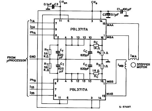
The PBL3717A stepper motor driver is a monolithic integrated circuit that controls and drives one phase of a bipolar stepper motor utilizing chopper control for phase current regulation. Current levels can be selected in three increments using two logic...
Warning: include(partials/cookie-banner.php): Failed to open stream: Permission denied in /var/www/html/nextgr/view-circuit.php on line 713
Warning: include(): Failed opening 'partials/cookie-banner.php' for inclusion (include_path='.:/usr/share/php') in /var/www/html/nextgr/view-circuit.php on line 713