
Improving USB 2.0 Switched-System Response
To optimize the performance of high-frequency circuits, the integration of discrete inductors in series with a device serves as a practical approach to managing capacitance. The primary objective is to fine-tune the circuit by selectively enhancing the response at specific frequencies, particularly the third harmonic. In this context, the MAX4906EF is utilized alongside additional board capacitance, which is estimated to be 12 pF.
The tuning process involves calculating the required inductance to achieve a peak response at 500 MHz. Given that the third harmonic of 240 MHz corresponds to a frequency of 720 MHz, the application of series inductance allows for the adjustment of the resonant frequency of the circuit. The formula for resonant frequency (f_r) in an LC circuit is given by:
f_r = 1 / (2π√(LC))
Where L is the inductance and C is the total capacitance. By rearranging this equation, it is possible to determine the necessary inductance to achieve the desired frequency response.
The choice of inductor value will be critical; it must be sufficient to counteract the capacitance without significantly affecting lower frequency signals. This selective tuning enhances the eye opening, which is crucial for high-speed digital signals, allowing for better signal integrity and reduced bit error rates.
In practical applications, the inductor should be chosen based on its quality factor (Q), as a higher Q will result in lower losses and better performance at the target frequency. Additionally, layout considerations should be taken into account to minimize parasitic capacitances and inductances that could adversely affect the circuit's performance.
Overall, this methodology provides a robust solution for enhancing the performance of high-frequency circuits while maintaining the integrity of lower frequency signals.By adding discrete inductors in series with the device, we can œtune out some of the capacitance, and improve the eye opening. If we add enough inductance to peak the 3rd harmonic of 240 MHz, with the capacitance of the device and any added board capacitance, we won t affect the lower frequencies much, and we ll enhance the performance where we need it.
If we assume that the MAX4906EF and the added board capacitance amounts to 12 pf, and we d like to peak the response at 500 MHz, then a small amount of series inductance will do just that.. 🔗 External reference
Related Circuits
Projects often involve numerous LEDs and microcontrollers; however, there is appreciation for simpler implementations using LEDs. One of the most basic LED circuits is... A basic LED circuit can be constructed using a single LED, a current-limiting resistor, and a...
Nowadays, USB is the most popular connection between PCs and peripherals such as AVR programmers, printers, scanners, etc. For that reason, it was necessary to modify an old serial AVR In-System-Programmer (ISP) to work with a USB connection. One...
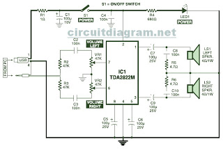
This is the circuit diagram of a USB-powered computer speaker, commonly referred to as multimedia speakers for PCs. The circuit features a single-chip design, operates on a low-voltage electrical power supply, is compatible with USB power from computers, and...
A pair of cross-coupled SCRs can be utilized to create a first-response monitor circuit, as illustrated in the schematic diagram below. The first-response circuit is... In the context of electronic monitoring systems, a first-response monitor circuit employing cross-coupled Silicon Controlled...
USB Battery Charger for Lithium Ion batteries using the LM3622 is a specialized charger circuit designed to operate with power sourced from a USB connection. The current consumption of the LM3622 is limited to 400mA by a resistor (R1),...
Stepper motors with unipolar drives are commonly utilized in applications that demand high torque and rapid positioning. The unipolar operation facilitates stable motor control through relatively simple firmware compared to bipolar drives. This application note examines the use of...