
Direct Coupled Radio Circuit with Diagram

The described circuit is a direct-coupled radio receiver designed to effectively operate with nearby radio stations. It primarily utilizes a transistor, denoted as Q1, which functions as the audio amplifier in the circuit. The direct coupling method allows for improved signal fidelity by minimizing distortion and ensuring that the audio signal is amplified without unnecessary frequency shifts.
In this schematic, the base-emitter capacitance plays a crucial role in radio frequency filtering. This capacitance forms a low-pass filter that helps to eliminate high-frequency noise, allowing only the desired audio frequencies to pass through to the output. The choice of components, including the transistor type and the values of resistors and capacitors, is essential for optimizing the performance of the circuit.
The circuit may include additional components such as resistors for biasing the transistor, capacitors for coupling and decoupling signals, and possibly inductors for tuning purposes. The layout should ensure minimal interference between components, particularly in the case of adjacent station reception, where selectivity is paramount.
Overall, this simple yet effective radio circuit design is suitable for hobbyists and engineers looking to explore the fundamentals of radio frequency amplification and filtering. Proper assembly and tuning of the components will result in an efficient radio receiver capable of picking up signals from nearby stations with clarity and minimal distortion.A simple direct coupled radio circuit diagram and schematic, ideal for adjacent stations.This circuit uses Q1 as audio amplifier and base emitter capacitance provides radio filtering.. 🔗 External reference
Related Circuits
This is a simple two-transistor lamp flasher circuit that can be used to flash a 6-volt lamp. The circuit is compact and can be easily fitted into a small enclosure. It utilizes two transistors: one is an NPN BC549,...
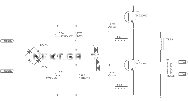
A small (2 to 3 meters) neon electronic transformer circuit diagram is provided below. The described circuit diagram is intended for use with neon lighting systems, specifically those requiring a transformer to operate efficiently within a range of 2 to...
Short circuits or broken PCB tracks can be easily identified using a multimeter. However, this tool may yield inaccurate results when assessing the efficiency of a transistor or diode unless the device is unsoldered and removed from the PCB....
The LM324N is part of the LM324 family, which includes four independent, high-gain, internally frequency-compensated operational amplifiers. These amplifiers are designed to operate from a single power supply over a wide range of voltages. Operation from split power supplies...
The circuit depicted in FIG. 1 generates a high-voltage signal for controlling the capacitance of barium strontium titanate (BST) capacitors. By applying voltages of V and 3V to the appropriate terminals, the capacitance of the BST can be modified....

This circuit was designed to control power delivery to a Peltier cooler in a vehicle. The power to the load from the vehicle's battery is managed by a Single Pole Double Throw (SPDT) relay. The circuit utilizes an SPDT relay...