
quick on board junction tester circuit diagram
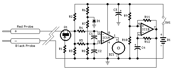
In electronic circuit diagnostics, the identification of short circuits and broken tracks on printed circuit boards (PCBs) is crucial for troubleshooting and maintenance. A multimeter serves as a fundamental tool in this process, allowing for the detection of continuity and resistance in the circuitry. When measuring the integrity of components such as transistors and diodes, the multimeter can provide misleading readings if these components remain soldered to the PCB. This is due to the influence of surrounding circuitry, which can alter the expected values.
To obtain accurate measurements, it is recommended that transistors and diodes be desoldered from the PCB prior to testing. This ensures that the multimeter readings reflect the true characteristics of the device without interference from other components. Additionally, the physical constraints of using a multimeter can complicate the testing process. The user must maintain a stable connection with the probes while also positioning the multimeter for visibility, which can lead to potential errors in reading.
For enhanced testing efficiency, alternative methods such as using a dedicated transistor tester or diode tester can be employed. These specialized devices are designed to measure the performance of semiconductors with greater accuracy and ease of use. They typically feature built-in displays that eliminate the need for awkward positioning of the multimeter, thereby streamlining the testing process.
Furthermore, incorporating automated testing systems can significantly reduce the manual effort involved in diagnosing PCB issues. These systems can perform multiple tests in succession and provide detailed reports on the condition of various components, thus facilitating quicker and more accurate troubleshooting. By leveraging advanced testing methodologies, the reliability of electronic circuits can be assured, leading to improved overall performance and longevity of the devices.Short circuits or broken pcb tracks can be easily recognized by means of a Multimeter, but this tool can give wrong results when testing the efficiency of a transistor or diode, unless the device under test is unsoldered and removed from the pcb. A further shortcoming affecting such way of testing is the necessity to keep firmly the probes on the pins of the device under test and at the same time to turn the head continually to read the Multimeter display..
🔗 External reference
Related Circuits
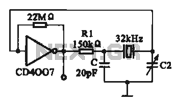
A 32 kHz clock oscillator is essential for digital circuits, as depicted in the schematic. The 32 kHz crystal clock oscillator serves to provide a time reference signal for the digital circuit. It utilizes a CMOS integrated circuit, specifically...
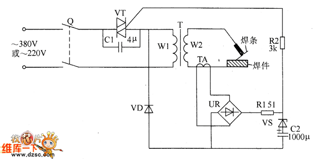
The welder no-load power saver circuit consists of a current detection control circuit and a power saving control circuit, as illustrated in the accompanying chart. The current detection control circuit includes a current transformer (TA), a bridge rectifier (UR),...
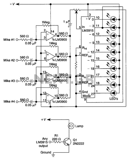
This circuit will produce an output when the sound exceeds a preset level. The LM3915 is a log-output bar graph driver. A transistor driver is used for higher current loads. To drive heavy-current loads with an LM3915 output, a...
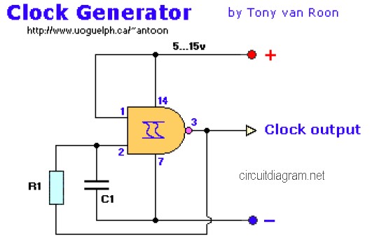
The following diagram is the clock generator circuit diagram built using NAND gate logic integrated circuits (ICs). The circuit can utilize either the IC 7400, which is a TTL type, or the IC 4011, which is a CMOS type....
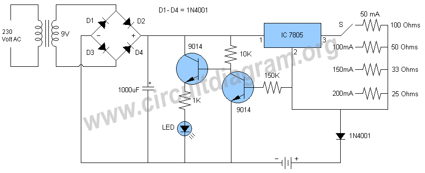
Schematic and description of a simple automatic NiMH battery charger circuit using IC 7805 with multiple selectable current options for charging. The described circuit is a straightforward automatic charger designed for Nickel-Metal Hydride (NiMH) batteries. It utilizes the IC 7805...
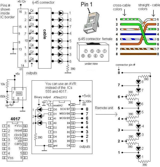
This LAN tester circuit was originally designed by Vassilis Stergiopoulos. It features two optional designs. The first design utilizes two main integrated circuits: the timer IC555 and the decade counter 4017. The second design is based on the microcontroller...