
Neon transformer circuit diagram
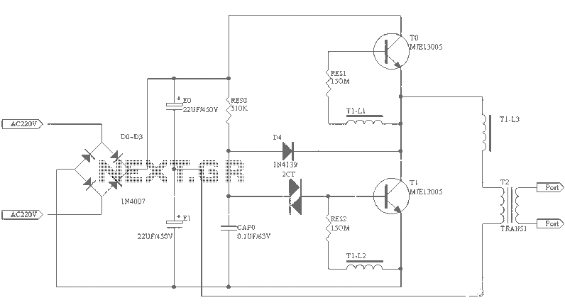
The described circuit diagram is intended for use with neon lighting systems, specifically those requiring a transformer to operate efficiently within a range of 2 to 3 meters. The electronic transformer serves to convert standard line voltage (typically 120V AC or 240V AC) to a lower voltage suitable for neon tubes, generally around 12V to 15V AC.
In the schematic, the primary components include the transformer itself, which is designed to handle the required load while maintaining the necessary output voltage. The circuit may also include a rectifier to convert the AC output to DC if the neon tubes require a direct current for operation, although most neon lights operate efficiently on AC.
Additional components in the circuit may consist of capacitors for filtering, ensuring a stable output voltage, and resistors for current limiting to protect the neon tubes from overcurrent conditions. An optional fuse can be incorporated for safety, preventing overcurrent situations that could lead to circuit failure or damage to the neon lights.
For effective operation, the transformer must be rated appropriately for the total wattage of the neon tubes being used. The layout of the circuit should ensure minimal distance between the transformer and the neon tubes to reduce voltage drop and maintain performance. Proper insulation and housing of the transformer and connections are also critical to ensure safety and reliability in operation.
This circuit is suitable for various applications including decorative lighting, signage, and architectural illumination, where neon lighting is desired for its distinctive glow and visual appeal.Small (2 to 3 meters) of neon electronic transformer circuit diagram as follows:
Related Circuits
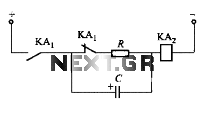
To fulfill the requirements of a control loop, it is often necessary to utilize an electromagnetic relay or a transistor relay to either accelerate or delay an action, thereby forming an acceleration or delay circuit. The circuit depicted in...
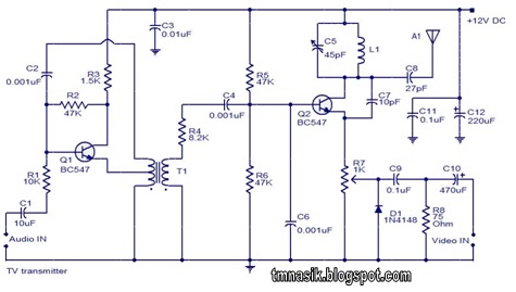
The TV transmitter circuit described utilizes UK standard 1 FM modulation for audio and PAL modulation for video. The audio signal intended for modulation is first amplified using transistor Q1 and its associated components. Transistor Q2 serves dual purposes:...
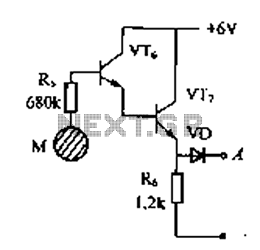
Delay electronic doorbell circuit - touch doorbell amplifier circuit The delay electronic doorbell circuit is designed to provide a user-friendly interface for doorbell activation, utilizing a touch-sensitive amplifier circuit. This circuit typically incorporates a touch sensor that detects user interaction,...

This design is for a thermometer circuit that utilizes the LM35 integrated circuit (IC) as a temperature sensor. It is a straightforward circuit that allows for the measurement of room temperature using a digital voltmeter or any voltmeter capable...
Sometimes when experimenting with different soundcards and MIDI interfaces it is useful to see if there is some data going in MIDI interface. This can be easily tested with this adapter, which converts the midi signals to visible light...

The infrared (IR) circuit is designed to control multiple devices using a TV remote. Unlike standard circuits that can typically switch only one device, this circuit allows for the operation of different devices with the same remote by utilizing...