
Direct Digital Synthesis Oscillator

The AD9835 is a highly integrated Direct Digital Synthesizer (DDS) that provides significant flexibility in frequency generation. It incorporates a Numerical Controlled Oscillator (NCO) that allows for precise frequency programming over a wide range, specifically from 0 Hz to 25 MHz when using a 50 MHz reference clock. The resolution of 0.01 Hz enables fine-tuning applications, making it suitable for various signal processing tasks, including RF applications and audio signal generation.
To construct the circuit, a 50 MHz crystal oscillator is connected to the clock input of the AD9835, which serves as the primary timing reference. The internal phase accumulator processes this clock signal to generate the desired output frequency. By utilizing a sine memory map, the synthesizer effectively converts the digital frequency information into an analog sine wave output via the integrated Digital-to-Analog Converter (DAC).
The output frequency can be adjusted through programmable registers, with the capability to change the frequency settings rapidly, making the AD9835 ideal for applications requiring quick frequency hopping, such as frequency scanning or agile receiver designs. The integration of two 32-bit frequency registers allows for dual frequency selection, enhancing operational flexibility.
The control interface of the AD9835 consists of three primary signals: FSYNC, SCLK, and SDATA. FSYNC is used to initiate data transfers to the device, while SCLK is responsible for clocking the data into the internal registers. The SDATA line carries the actual data being sent to configure the frequency and phase settings.
The internal architecture also includes phase registers that allow for phase adjustments of the output signal if needed. However, for many applications, the phase may remain fixed, simplifying the configuration process. The overall design of the AD9835 supports a wide range of applications, from simple tone generation to complex modulation schemes in communication systems, making it a versatile component in modern electronic design.The AD9835 combines the Numerical Controlled Oscillator (NCO), COS Look-Up Table, Frequency and Phase Modulators, and a Digital-to-Analog Converter on a single integrated circuit. With more easy words you can say that this circuit is a oscillator where the frequency can be programmed from 0 to 25 MHz with the resolution of 0.01Hz!
Here you will also be able to download controling software for your own projects. DDS stands for Direct-Digital Synthesis. This synthesizer is simply a circuit that can create a sine- wave signal from a reference crystal and a programable frequency-register. All this circuit needs is a reference oscillator (crystal) and some filter. See fig above: A crystal oscillator (50MHz in my case) is connected to the input (Clock in) of the DDS.
The phase accumulator calculate the frequency you want the output to have. A sine memory map send data to the D/A and at the output you will have a sinus-signal with the desired (programmed) frequency. You can program the output frequency from 0Hz to 50MHz, but according to the sampling theory (Shannon, Nyquist) practically, the output is limited to about 45% of the maximum clock rate at which the logic can be operated.
This means that the sinus-output can reach from 0 Hz to about 25MHz with a 50MHz crystal. I think that is really good. Inside the DDS is a programable divider wich divid the Clock in with 232 and multiply it with a programable register. Lets say you want to build a 6M (50MHz) fine tuned receiver and maybe you want it to be a digital tuning. (See pic above). Now, the first mixer mix the input frequency with a crystall controlled frequency so from this mixer you will get an IF about 10MHz.
Next mixer will mix the IF with the DDS frequency 0-20 MHz and the output is demodulated to an audio signal. If you program the DDS so the output is almost 0 Hz you will receive at 40MHz and if you program the DDS so the output is 20MHz you will receive at 60MHz.
Conclusion: With the DDS you will now be able to tune the receiver from 40MHz to 60MHz. The smallest stepsize will be 0.011Hz. That is amazing! The Registers in the DDS can be changed with a few micro seconds, so you can jump between different frequency really fast. Maybe you want to build a scanner wich scann really fast, the you should use a DDS. A PLL-synthesizer will never be as fast. The pic above shows the internal block in the chip. Lets start with the yellow part. There are two 32 bits registers wich can set the divider ration FREQ 0 REG and FREQ 1 REG. You can choose wich register you want to be present for the phase accumulator by the register SELSRC (Select Source Bit).
IF SELSRC is = 0 the selection of register is made by the FSELECT pin on the AD9835. IF SELSRC is = 1 the selection of register is made by the bit (internal register). In most cases one only need 1 register, so I have choose to set the SELSRC = 0 and I choose to use FREQ 0 REG by conect the FSELECT pin to GND. The blue part shows the phase register. There is 4 different registers wich all contains the phase of the signal. These register can also be selected by two pin on the ic or by two registers. IF SELSRC is = 0 the selection of the phase registers are made by the PSEL 0 and PSEL 1 pins on the AD9835.
IF SELSRC is = 1 the selection of the phase register is made by the bit (internal register). I never need to change the phase, so I have set the SELSRC = 0 and conected the pins PSEL 0 and PSEL 1 to GND. For futher data see the datasheets. The green part is the hart of the DDS. It is here the sinus signal is built up. The purple part is the controlling unit. FSYNC, SCLK and SDATA are for setting the registers. FSYNC must go low to send data to the DDS. SCLK clocks data into the DDS and the SDATA is the data to the DDS. Maybe you want to build a sweep oscillator to tune your IF filter or crystal filter (0-25MHz), then a DDS is perfect for you.
You can also use the DDS to build a programable low frequency tone generator. My next DDS project will be a police scanner that scann from 79 to 81 MHz. It is only a few MHz and a DDS will really make it fast scanning. The nice with that project is that I dont need to find an exact 69MHz crystal for the first mixer since I can program the DDS. 🔗 External reference
Related Circuits
This is a voltage controller oscillator that was designed as a wide range oscillator to generate clock pulses for a stepper motor drive system. It does however have some interesting features. The original application used a stepper motor for...
Regenerative feedback at capacitor C allows the oscillator to complete its timing cycle instead of shutting off immediately. The integrated circuit (IC) used was a CD4011AE, although an equivalent IC will also function. The described circuit utilizes regenerative feedback to...
The digital lock shown below uses 4 common logic ICs to allow controlling a relay by entering a 4 digit number on a keypad. The first 4 outputs from the CD4017 decade counter (pins 3,2,4,7) are gated together with...
This is a variable power supply controlled by a PIC microcontroller. An LCD display is included in the circuit to show the actual output voltage and current values. A push-button switch is used to adjust the output voltage and...
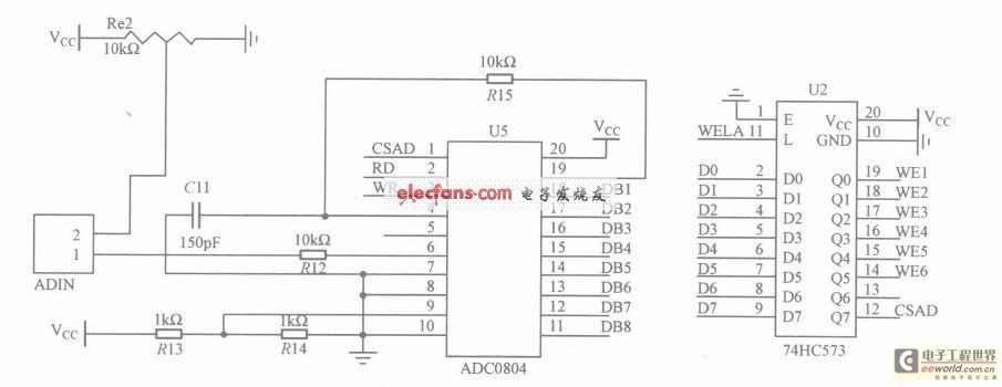
The circuit utilizes the ADC0804, which is configured for left-handed operation, alongside the 74HC573 latch, which is configured for right-handed operation. The latch is connected to a microcontroller, but they are not drawn in the same schematic. The CSAD...
Construct the Colpitts oscillator using either a breadboard (prototype board) or stripboard, and then verify its operation with a multimeter and oscilloscope. This Colpitts oscillator generates a sine wave output exceeding 12V peak-to-peak at a frequency determined by the...