
Power Control Unit
The power control unit circuit diagram illustrates the primary components and their interconnections for managing electrical power within a system. The main relay, positioned on the left side of the schematic, serves as the central control element, activated by the key switch. This relay is responsible for enabling or disabling the flow of power to various subsystems based on the user's input through the key switch.
The circuit typically includes additional elements such as fuses for overcurrent protection, diodes for flyback protection, and possibly indicator LEDs to show the operational status. The key switch usually connects to the relay coil, ensuring that when the key is turned to the 'on' position, the relay is energized, closing its contacts and allowing current to pass to the downstream circuits.
In more complex designs, auxiliary relays or contactors may be included to manage higher power loads or to provide additional control features. The layout of the circuit should ensure that all components are properly rated for the expected voltage and current levels, with appropriate wire gauges and connection methods to ensure reliability and safety. Each component should be clearly labeled in the schematic to facilitate understanding and troubleshooting by technicians or engineers who may work with the circuit in the future.This a shows the overall circuit diagram of the power control unit. On the left, there is a main relais controlled by the key switch and the .. 🔗 External reference
Related Circuits
This must be the most efficient bipolar transistor motor driver design for this application and I recommend it for the solar roller competitions. A 1381E is used to trigger at 2.4V. While it takes a total of 10 components...
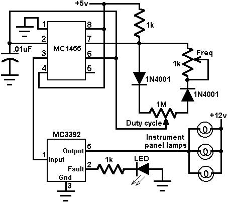
This circuit utilizes an MC3392 low-side protected switch along with an MC1455 timing circuit to create a dimmer control for automotive instrumentation panel lamps. The brightness of incandescent lamps can be adjusted by applying Pulse Width Modulation (PWM) to...
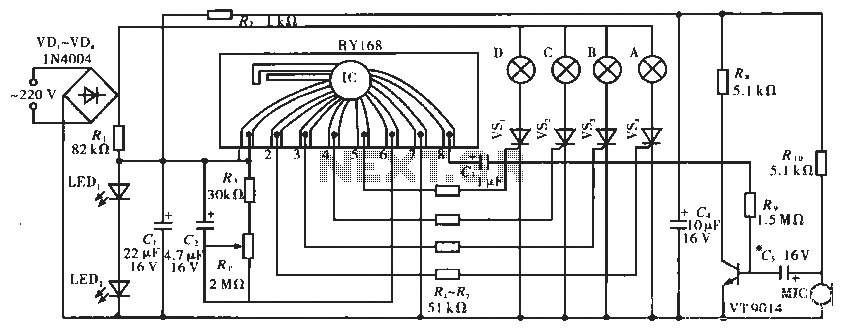
The circuit operates with a controller that includes a power supply circuit, a control circuit, and an audio amplifier, which are three distinct components. The power circuit comprises diodes VD1 to VD4, resistor R1, capacitor C1, LED1, LED2, and...
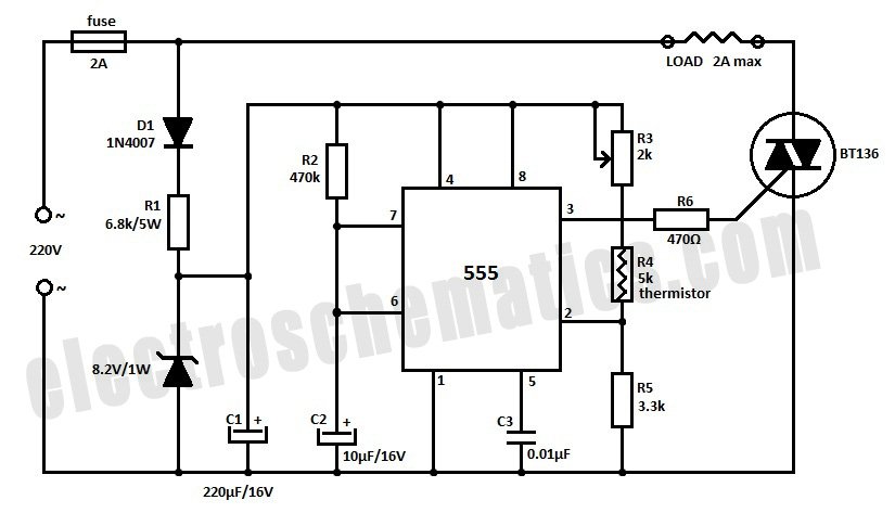
Construct a temperature controller circuit using the 555 integrated circuit (IC) in combination with a thermistor resistor divider. The benefit of this design is that it does not require a well-regulated power supply. The resistor divider network comprises an...
48 V phantom powering has become the standard for professional condenser microphones. The supply (or rather bias) voltage is applied over both wires of the microphone cable. Phantom power is a method used to provide power to condenser microphones through...

If the total circuit resistance can be significantly reduced to less than 0.1 Ohm and a load of 0.4 Ohm or less is connected, over 1 kilowatt of free electrical energy can be obtained. There are two discrete voltage...