
; Distribution Amplifier
A distribution amplifier is a critical component in various electronic systems, serving to replicate and distribute signals across multiple outputs while maintaining signal integrity. The architecture typically includes a preamplifier stage followed by multiple buffer stages. The preamplifier stage is designed to provide initial gain and may include adjustable resistors to customize the gain based on application requirements. The use of a capacitor at the input is essential for DC blocking, ensuring that only AC signals are processed, which is particularly important in audio applications where DC offsets can distort the signal.
The subsequent buffer stages, configured as voltage followers, ensure that the output signals maintain the same voltage level as the input without introducing additional gain. This configuration effectively isolates the input from the outputs, preventing loading effects that could degrade signal quality. The choice of operational amplifier, such as the TL084, is crucial as it provides the necessary bandwidth and performance characteristics for audio applications. The operational amplifier's quad configuration allows for compact design, reducing the overall footprint of the circuit while providing multiple amplification stages.
In designing a distribution amplifier, careful consideration must be given to the impedance matching of the circuit. The choice between 50 ohm and 75 ohm configurations typically depends on the application, with 75 ohms being common in video applications and 50 ohms often used in RF and audio contexts. The output load resistors and capacitors play a significant role in determining the frequency response and stability of the amplifier, necessitating precise selection based on the intended use.
In summary, distribution amplifiers are versatile devices that can be tailored to meet the specific needs of various signal types, ensuring reliable and high-fidelity signal distribution across multiple outputs. Their design must consider factors such as gain, bandwidth, impedance, and signal integrity to achieve optimal performance in a wide range of applications.Although a distribution amplifier may accept different input channels and output those to particular outputs. The term is meant to describe something that outputs the same signal to some number of outputs,based on one input.
The outputs are identical, and the signals all appear or transition at the same time. A similar approached is used with some IC functions, an example would be a 1-to-10 Clock Buffer, used for clock distribution. Many other logic functions exist to provide minimum signal skew between outputs and eliminate the fanout problem of driving multiple outputs. IC Decoders are another form of signal distribution. Semiconductor Analog Switches are also used to distribute, or fan out signals to more than one location.
As a piece of equipment, a distribution amplifier could come in many forms. The distribution amplifier might be designed to fan-out audio signals, video signals or digital signals, and in each case being a completely different design. At the circuit level the amplifiers, or drivers, could be 50 ohm or 75 ohms and might be called lines drivers or cable drivers.
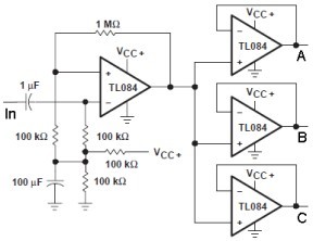
At the circuit level the distribution amplifier would take on the form of the clock buffer example but would use ICs of what ever type would have the correct interface level. For example TTL ICs for digital logic signals or operational amplifiers for analog signals. The circuit fragment above is meant to represent a distribution amplifier used in the audio range. The capacitor values have been selected to have an effect in the audio frequency range, but they could be altered to change the frequency range.
The operational amplifier used in the circuit is a TL084 which has a unity gain bandwidth of 3Mhz. The TL084 was selected because it`s a quad package and carries all four of the required operational amplifiers. However any operational amplifier, including a 741 Op Amp, would work as long as the bandwidth of the amplifier matched that of the frequency of interest.
The data sheet indicates a 14 pin DIP package or 20 pin flat pack, which indicates the age of the device [no SOIC option]. The first operation amplifier is intended to be a preamplifier and has a gain of ten. However the gain may be changed by adjusting either the 1Meg or 10k resistors. The input is applied through a 1uF capacitor to block any DC from the previous stage. However as this component may not be required, or reside in the preceding circuit, so may be left out.
The three distribution amplifiers are each unity gain voltage followers. The circuit diagram was modified from an example in an application note, or application book. The original circuit, dating back to the 1980`s also used 50uF capacitors and 5. 1k load resistors on the output of each of the buffers [neither is shown here]. 🔗 External reference
Related Circuits
The power amplifier Hi-Fi OCL 120W RMS is designed to operate effectively when paired with a suitable power supply circuit and 8-ohm speakers. This circuit exclusively utilizes transistors without any integrated circuits, resulting in a clean sound output. The...

This is a simple headphone amplifier circuit designed to drive headphones when a music player lacks sufficient power. The circuit is straightforward and utilizes only three transistors. The first transistor, Q1 (BC 239), along with its associated components, functions...
Used when maximum input impedance is required or when the signal attenuation of the voltage divider volume control is undesirable. In electronic circuit design, achieving maximum input impedance is often critical, particularly in applications involving sensitive signal processing. The use...
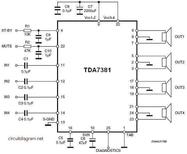
The TDA7381 is a Class AB audio power amplifier housed in a Flexiwatt25 package, specifically intended for car radio applications. This circuit can also be utilized for various other purposes. The fully complementary PNP/NPN output configuration enables a rail-to-rail...
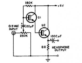
This schematic diagram illustrates a simple headphone amplifier circuit constructed using two NPN transistors. Suitable transistor options include the BC549C, as well as other NPN transistors such as the European equivalents BC548C, BC547C, BC239, 2N5818, or 2N2222. An audio...
This preamp is very simple, and will work under tough conditions. The input impedance is pretty high, so it won't load down electric guitars. It will also amplify microphones. When there is a moment, there will be some additions that...