
Dive Computer interface RS232
The described circuit serves as an interface for a dive computer utilizing the RS232 communication protocol, incorporating the MAX232A integrated circuit. The MAX232A is a dual voltage-level converter that facilitates communication between devices operating at different voltage levels, specifically converting TTL (Transistor-Transistor Logic) levels to RS232 levels and vice versa.
In this application, the dive computer likely operates at TTL levels (typically 0V to 5V), while the RS232 standard operates at higher voltage levels, ranging from +3V to +25V for logical '1' and -3V to -25V for logical '0'. The MAX232A enables seamless communication between the dive computer and other RS232-compliant devices, such as a PC or a data logger.
The circuit typically consists of the MAX232A chip, several external capacitors for charge pump operation, and the necessary RS232 connectors (DB9 or DB25) to interface with other devices. The external capacitors, often 1µF to 10µF, are connected to the charge pump pins of the MAX232A to generate the required positive and negative voltage levels for RS232 communication.
Pin configuration of the MAX232A is crucial for proper functionality. The chip features multiple pins designated for TTL input and output as well as RS232 output. The circuit design should ensure that the TTL signals from the dive computer are connected to the appropriate input pins of the MAX232A, while the RS232 outputs are routed to the connectors.
In practice, the circuit will require careful attention to grounding and signal integrity to avoid communication errors. Proper layout considerations, such as minimizing trace lengths and avoiding cross-talk, will enhance the reliability of data transmission in this dive computer interface.This circuit represents a Dive computer interface for RS232. Uses the MAX232A. 🔗 External reference
Related Circuits
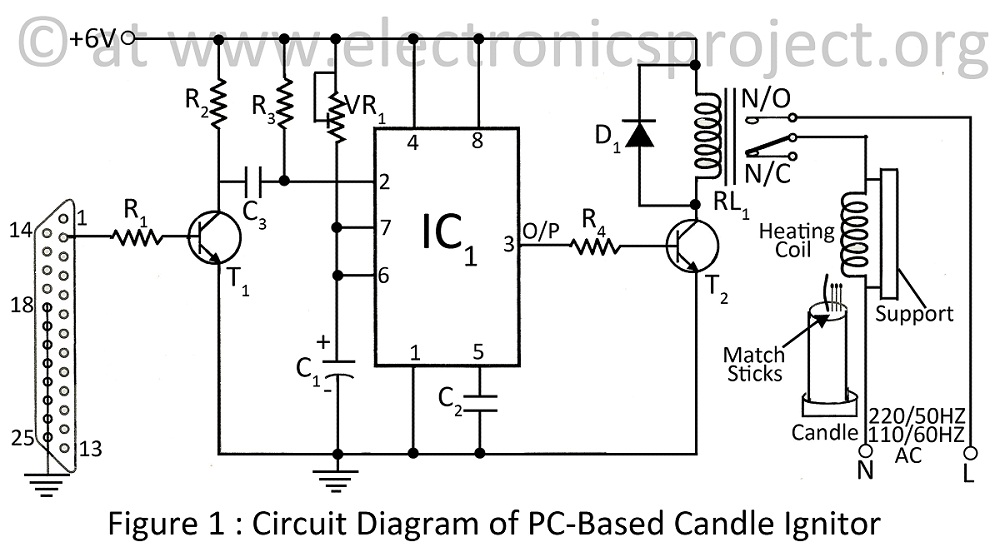
A PC-based candle ignitor is a verified project designed for computer students, utilizing a 555 timer circuit to ignite a candle. The project includes a computer circuit diagram and software code written in C. The PC-based candle ignitor project integrates...
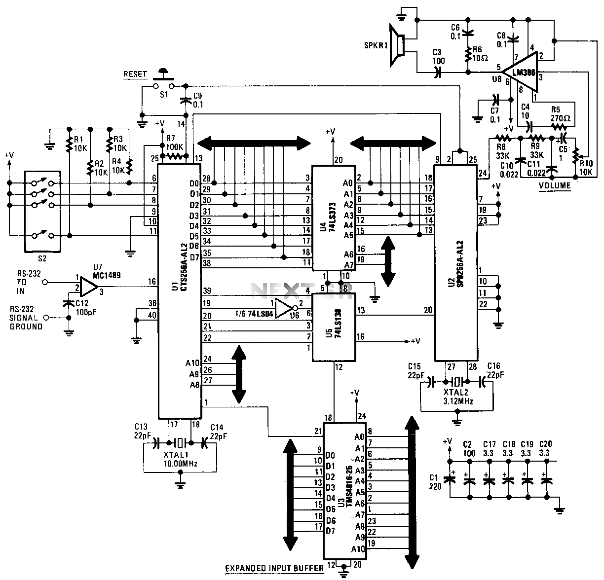
This text-to-speech converter is constructed using the SP0256-AL2 speech processor and the CF6256AL2 text-to-speech converter chips manufactured by General Instruments. The circuit is designed to receive standard ASCII code from virtually any microcomputer or dumb terminal equipped with an...
The PIC16C57-RCT is a communication single-chip microcomputer integrated circuit that is commonly utilized in the Qiao Xing series of IC card management telephones. The PIC16C57-RC integrated circuit features a pulse and dual-tone dialing circuit, memory data and clock circuit,...
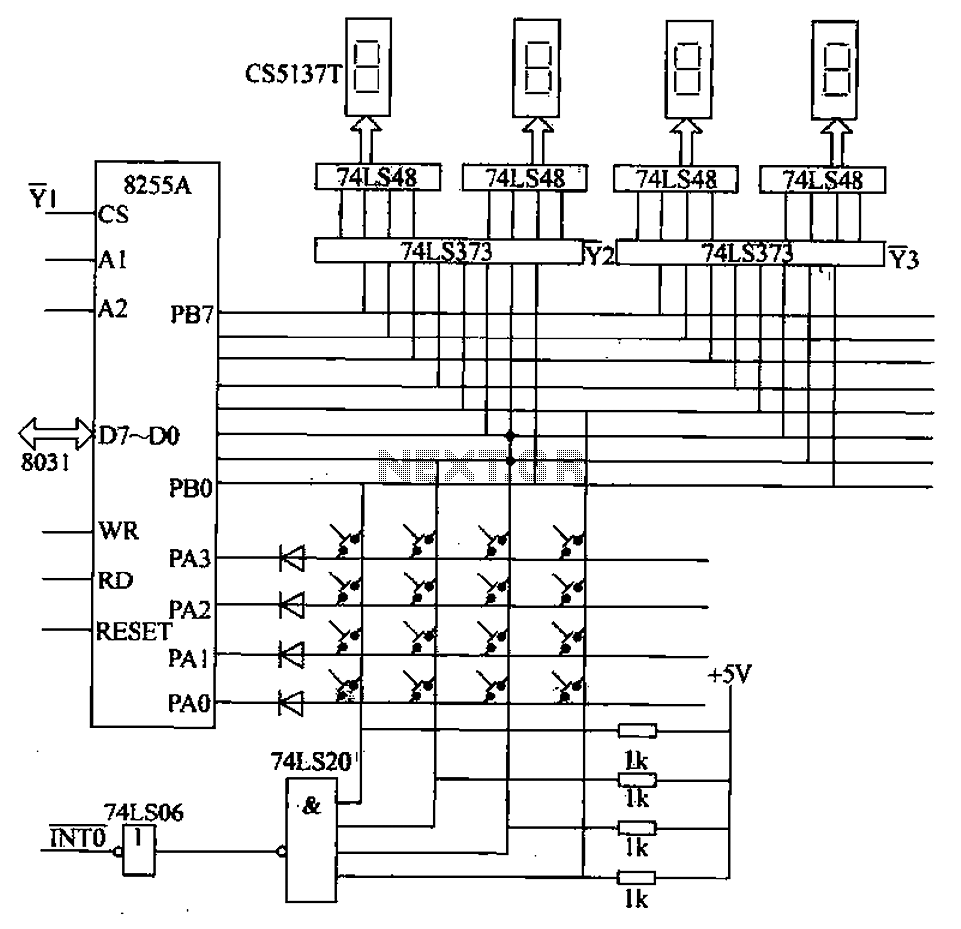
A 4x4 matrix keyboard system is designed for parameter settings, featuring numeric keys from 0 to 9 and function keys labeled A to F. The primary functions of the keyboard include completing parameter settings, selecting display modes, starting automatic...
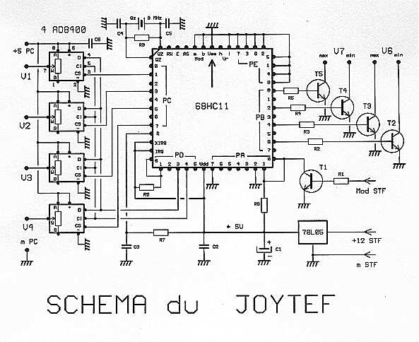
Using the software during flight simulation models of planes: REAL-FLIGHT, we first chose a housing of any transmitter empty direct connection potentiometers innings. However, this is not good because, first races of the potentiometers are only 90 degrees, which...
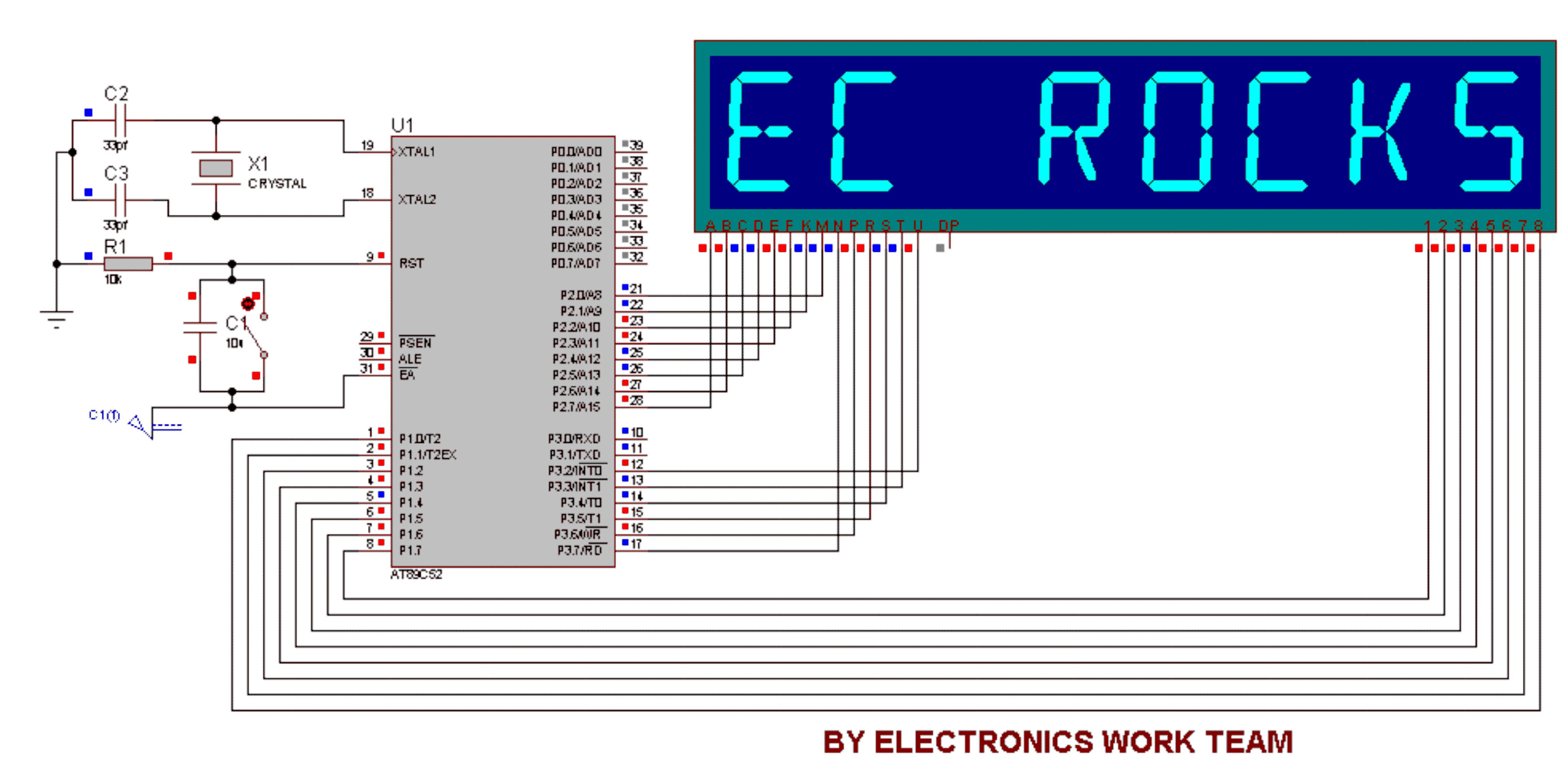
This circuit utilizes a 14-segment display to represent characters. The 14-segment display consists of 22 pins, which facilitate the display of various characters. Eight pins labeled A, B, C, D, E, F, K, and M are connected to the...
Warning: include(partials/cookie-banner.php): Failed to open stream: Permission denied in /var/www/html/nextgr/view-circuit.php on line 713
Warning: include(): Failed opening 'partials/cookie-banner.php' for inclusion (include_path='.:/usr/share/php') in /var/www/html/nextgr/view-circuit.php on line 713