
PC-BASED CANDLE IGNITOR lighting candle using computer

The PC-based candle ignitor project integrates hardware and software components to allow a computer to control the ignition of a candle using a 555 timer integrated circuit (IC). The 555 timer is configured in a monostable or astable mode, depending on the desired functionality, to generate a pulse that can trigger a relay or a transistor. This relay or transistor acts as a switch to control a heating element or ignitor that ignites the candle.
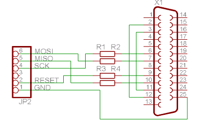
The circuit diagram typically includes the 555 timer connected to various components such as resistors, capacitors, and a control mechanism that interfaces with the computer. The computer communicates with the circuit through a serial or parallel interface, sending commands to activate the 555 timer. The software code written in C is responsible for user input, processing, and sending signals to the hardware.
In a practical application, the user can initiate the ignition process through a graphical user interface (GUI) on the computer. The software may include safety features such as timers or confirmation prompts to ensure safe operation. The overall design emphasizes reliability and safety, making it suitable for educational purposes and demonstrations of electronic control systems.
This project serves as an excellent learning tool for computer students, providing hands-on experience with both hardware circuitry and software programming, reinforcing concepts in electronics and embedded systems.PC based candle ignitor is a pc based verified project for computer student using 555 lighting candle using computer circuit diagram with software code in C . 🔗 External reference
Related Circuits

In certain industries, a computer-controlled 4-20 mA current loop is utilized to manage various equipment. This current loop is employed to transmit a signal over a distance. The 4-20 mA current loop is a standard method for transmitting analog signals...

The telephone ring generator described generates the necessary aerial voltage using a simple switched-mode power supply (SMPS). It incorporates a CMOS Schmitt Trigger-based oscillator, a 10 mH inductor, a high-voltage switching transistor (such as the TIP47 or another high-voltage,...
The Atmega 128 is similar to other AVR microcontrollers. It is in-system programmable (ISP). An earlier article discussed the AVR ISP programmer, which utilizes a 74HC244 buffer for safety when programming the AVR. However, if a programmer for the...

For the last year, a prototype for a solar inverter that can be grid-intertied has been developed. A solar inverter converts 12V DC (or other voltages) from solar panels. The solar inverter is a crucial component in photovoltaic systems, responsible...

This is a water sensor alarm circuit designed to warn users about water levels. It activates an audible alarm when the sensor comes into contact with water, such as during rainfall. The water sensor alarm circuit functions primarily as a...

The objective of this project is to develop a device capable of outputting VGA signals to a CRT monitor to display figures, text, and characters. The project involves designing a circuit that generates standard VGA signals, which include separate horizontal...