
Keyboard - Display Interface Circuit
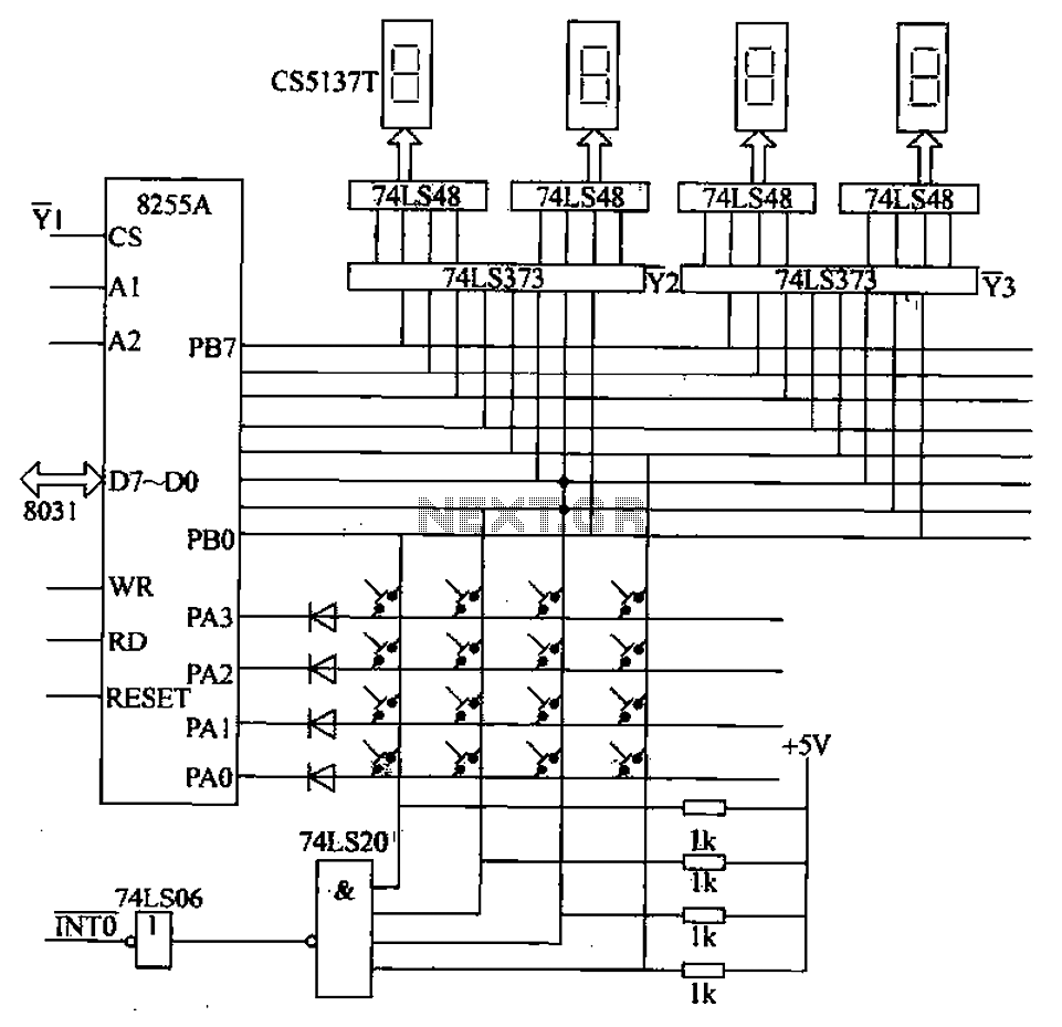
The 4x4 matrix keyboard system is structured to facilitate user interaction with the microcontroller, allowing for versatile control of various parameters. Each of the numeric keys (0-9) and function keys (A-F) is arranged in a matrix format, which enables efficient scanning and detection of key presses. The implementation of the 8255A programmable interface chip is crucial, as it manages both input from the keyboard and output to the display, ensuring seamless communication between the user interface and the microcontroller.
In terms of functionality, the keyboard is capable of initiating different operational modes, including automatic or manual arrangements, which could be critical for applications requiring user-defined settings. The static display, driven by the 74LS48 decoder/driver, presents the selected parameters clearly to the user, while the 74LS373 latch maintains the state of the display during operation.
The keyboard matrix is scanned by the microcontroller through the designated ports of the 8255A. When a key is pressed, the corresponding row and column are activated, allowing the microcontroller to identify which key has been pressed. This information is crucial for executing the appropriate command, whether it be adjusting parameters or selecting different operational modes. The dual functionality of the 8255A port B, switching between output and input modes, enhances the efficiency of the system, allowing it to respond promptly to user inputs while simultaneously providing visual feedback through the display.
Overall, the design of the 4x4 matrix keyboard system, in conjunction with the 8255A programmable interface chip and associated components, creates a robust and user-friendly interface for managing various system settings and operations.4X4 matrix keyboard system settings, including 0 ~ 9 numeric keys. A ~ F as function keys. The main function of the keyboard is complete parameter settings, display mode select ion, start automatic/manual arrangements, as well as the system and stop. Keyboard and display interface chip 8255A programmable circuit and connected to the microcontroller circuit shown in Figure 27-48. from this picture, you can see. 8255A to the B port as the display interface. The system uses a static display, 74LS373 as a latch. 74LS48 for the common cathode decoder/driver, LED digital tube with CS5137T. 44 keyboard matrix keyboard. 8255A port PA3-PAO row scan connection port column values from port B PB3 ~ PBO read people, to deal with the system keyboard interrupt.
Thus, 8255A port B to work in two ways under: In the display state is output; the keyboard interrupt service routine processing input mode. To do this, just in front of the corresponding operation re 8255A new settings work.
Related Circuits
This time, we will share information about Yo3dac's homebrew RF circuit design ideas, including the latest updates from Onmilwiki. Yo3dac is known for innovative approaches in the realm of radio frequency (RF) circuit design, particularly within the homebrew community. The...
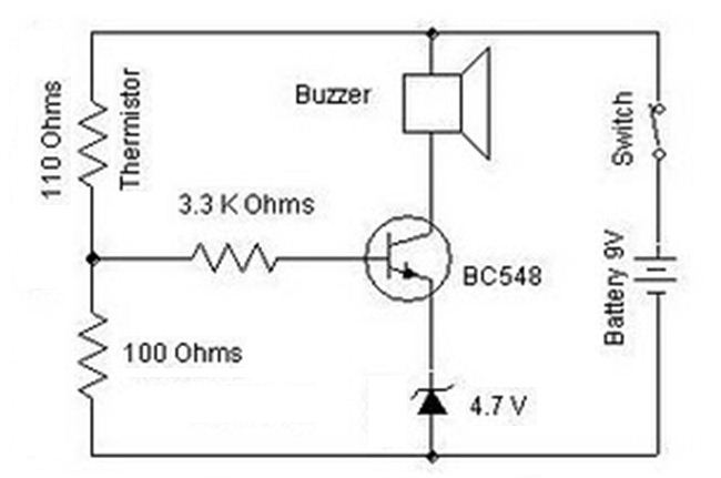
A heat sensor circuit can be utilized to control any device using a heat sensor. In this circuit, a thermistor and a resistor are connected in series, forming a potential divider circuit. The thermistor is of the Negative Temperature...
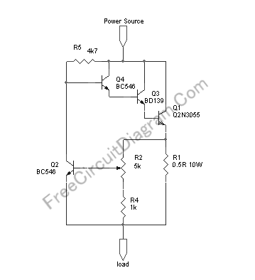
This circuit provides automatic current limiting up to 8.4 A. Unlike current limiters that use only a resistor, this current limiting circuit does not drop the voltage significantly or keeps the voltage drop to a minimum until a specific...
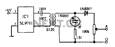
The electronic frostbite treatment instrument ASIC SL9711 consists of an oscillation circuit, a power amplifier, and a controller. It generates a sine wave at frequencies of 100 Hz and 3 Hz, followed by a step-up transformer with potentiometer adjustment...
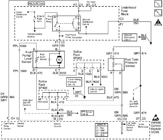
The control module monitors the fuel tank pressure (FTP) sensor signal to detect vacuum decay and excess vacuum during the enhanced evaporative emission (EVAP) diagnostic. The Fuel Tank Pressure Sensor responds to changes in the fuel tank pressure or...
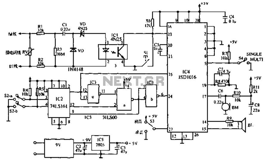
The call is made using the ISD1016 language chip for voice generation instead of a traditional phone ringing message controller schematic circuit. This controller can store messages, music, songs, or other sounds, serving as an alternative to monotonous ringing. The...