
DIY FM Radio Kit
The FM Radio kit from Velleman-Kit presents an engaging opportunity for individuals to develop soldering skills while constructing a functional electronic device. The assembly process emphasizes the importance of precision in soldering, particularly when dealing with small components such as IC sockets and diodes. Each component's placement is critical for the overall functionality of the radio, and the instructions guide the user through the necessary steps to ensure correctness.
The circuit board layout is designed to facilitate easy identification of component positions, with clear markings for resistors, capacitors, diodes, and IC sockets. The inclusion of a voltage regulator is essential for maintaining stable operation, and attention to the orientation of components like the LED and capacitors is necessary to prevent malfunction.
When soldering, it is advisable to use a fine-tipped soldering iron to minimize the risk of excess solder and potential short circuits. The assembly process not only reinforces technical skills but also enhances understanding of basic electronic principles, such as circuit connectivity and component functionality.
Upon completion, the integration of the speaker and antenna provides the final touch needed for the radio to operate effectively. The simplicity of the design, combined with the satisfaction of achieving a working radio, makes this kit an ideal project for novices in electronics. Following the assembly, users are encouraged to explore tuning frequencies and understanding signal reception, further enhancing their learning experience in the field of electronics.I recently bought an FM Radio kit made by Velleman-Kit and sold by Radioshack. I have not had time to build it but this Thursday, I sat down, played some Doctor Who on my Kindle Fire HD, and built this kit with my solder iron and solder. Total time took me two hours (the reason for this is because I kept getting distracted with Doctor Who).
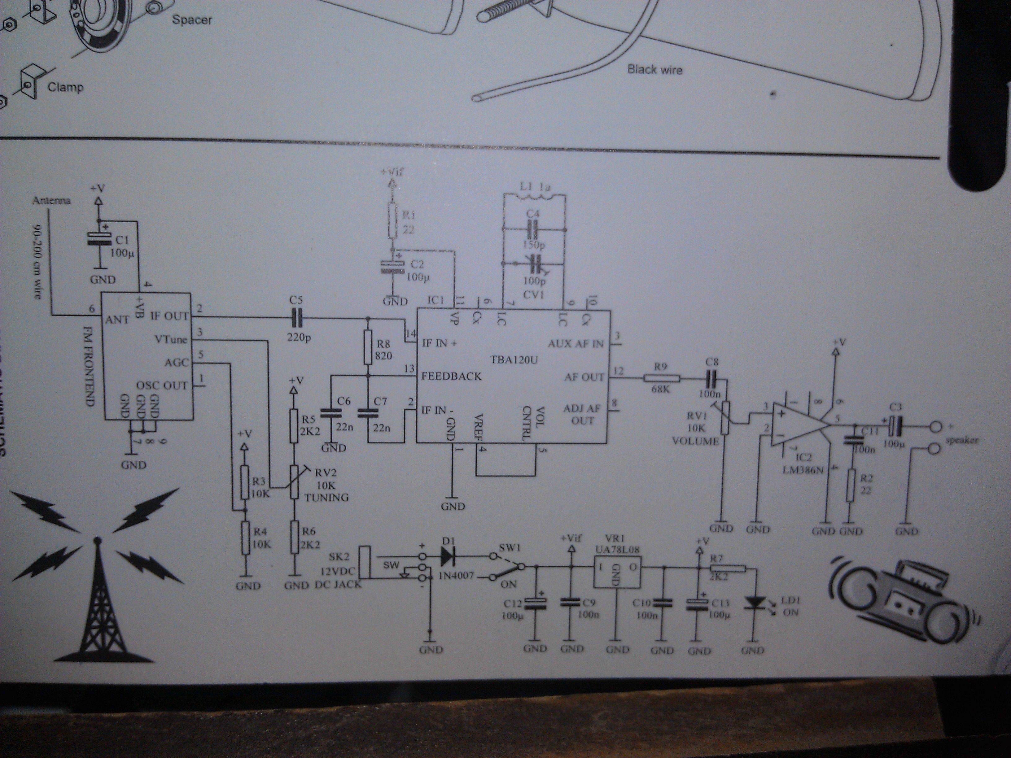
The i nstructions are fairly easy to understand, however, instructions are not explicit in that you have to make the connection to solder the components to their respective position. I`ll try to explain as close as possible how to build this fun little project. The components that came with the FM radio kit are as follows. The diagram tells you which resistor to solder to which circuit position on the circuit board. For example, the 22 ohms resistor should be soldered on R1 and R2 positions on the circuit board. There is only one diode you have to solder on and it is on position D1. Make sure that you watch the polarity because if it is inserted wrong, it will not work. Because of the tiny pins located on the bottom of the IC sockets, you must be very careful with soldering.
There is a chance you can use to much solder and cause a solder bridge between pins. The 14 pin socket is in position IC1 while the 8 pin is in IC2. Make sure the position of the notch on the socket matches the diagram on the circuit board. Make sure that the regulator goes on position VR1 and also that the flat portion of the regulator is on the same side of the flat line diagram on the circuit board. There is only one LED in the kit and the manual says it should be put on LD1 position; however, on my board there is no LD1 position so instead put it in the position that says ON.
Make sure the cathode (the longer lead) is inserted in the hole that has the white stripe. These are a different type of capacitors than the ones used in step 5. These are placed in positions C1, C2, C3, C12, and C13. Make sure that the cathode is placed through the correct hole or else it might not work. The FM Front End is given by Velleman so I do not know if one can make their own. The position to solder this is on is the designated area. Basically, you will know where it is by looking at the circuit board. Remember the IC Sockets we soldered in step 4 We now insert both the 14 pin and 8 pin ICs into the sockets. Make sure the notch matches the same notch side on the sockets. The last step is to install the speaker onto the circuit board, mount it using the screws and nuts, then connect the positive and negative terminals of the speaker to the circuit board, and finally solder on the black wire that will act as the antenna.
Should be fairly simple and by this time you should be fairly familiar with the circuit board to know where these components need to go. By this step you should be done with your FM radio and the only thing that needs to be done is plug in a 12V power connector, turn the radio on, and tune in to your favorite FM station.
That project was very fun to make and it was a good starter project to get someone into the world of soldering. Have a project you want me to try Let me know by commenting below. 🔗 External reference
Related Circuits
UART, GPS. This application note illustrates how to integrate a GPS module SC16C2552B into a navigation system using a Philips UART. With the rapid advancement of GPS (Global Positioning System) technologies, GPS is being increasingly utilized across various sectors....

For maximum mini-security, this RC Tupperware Turret delivers a formidable deterrent against food theft. While it lacks motion sensors, potential food thieves will think twice before attempting to swipe baked goods. This 11-hour project, designed by Chris of PyroElectro,...
In the absence of radiation, no current is drawn. At normal background radiation levels, the power consumption is extremely low. The instrument may be left on for several months without changing batteries. In this way, the detector is always...
Create a rapid transmitter/receiver pair that can be found in most households. An AM or FM radio system is suitable since it is widely accessible. The design focuses on generating the required radio signal and modulating it effectively. After...
This circuit will filter out interference signals and ensure that the signal received from the Morse code station stands out. The described circuit functions as a signal processing system specifically designed to enhance the clarity of Morse code transmissions by...
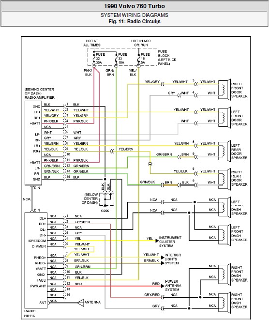
The following document contains the system wiring diagram of the radio circuit for the Volvo 760 Turbo 1990. Please note that this is a system wiring diagram, not a schematic diagram. Download the radio circuit system wiring for the...