
Simple Ham Radio Circuit Audio Filter With 741 IC
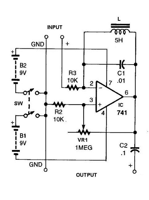
The described circuit functions as a signal processing system specifically designed to enhance the clarity of Morse code transmissions by minimizing the impact of unwanted interference. The primary components of this circuit typically include a bandpass filter, an amplifier, and a demodulator.
The bandpass filter is crucial in allowing only the desired frequency range associated with Morse code signals to pass through while attenuating frequencies outside this range. This is essential for isolating the Morse code signal from background noise and other unwanted signals.
Following the filtering stage, the amplified signal is directed to an amplifier. The amplifier boosts the filtered signal to a level suitable for further processing. This stage is vital in ensuring that the signal strength is sufficient for the demodulation process, which converts the modulated Morse code signal back into a readable format.
The demodulator then interprets the amplified Morse code signal, converting it into a format that can be understood by the receiving equipment or operator. This may involve translating the signal into audio tones or visual representations, allowing for effective communication.
In summary, this circuit is designed to enhance the reception of Morse code signals by filtering out noise and interference, amplifying the desired signals, and processing them for clear communication. This comprehensive approach ensures reliable Morse code transmission and reception in various operational conditions.This circuit will help to filter out the interference signal and ensure that the signal received from the Morse code station stand out. The .. 🔗 External reference
Related Circuits
This compact device serves as a replacement for the input transistors and related circuitry on a single TO-220 style package. A decision was made to substitute the original driver board with a newly fabricated printed circuit board (PCB) designed...
This Intercom is powered by two 9-volt batteries and uses only current when the Intercom is used. Both units are connected via a two-wire little cable or simply two wires (dotted lines). The loudspeakers act both as loudspeakers and...
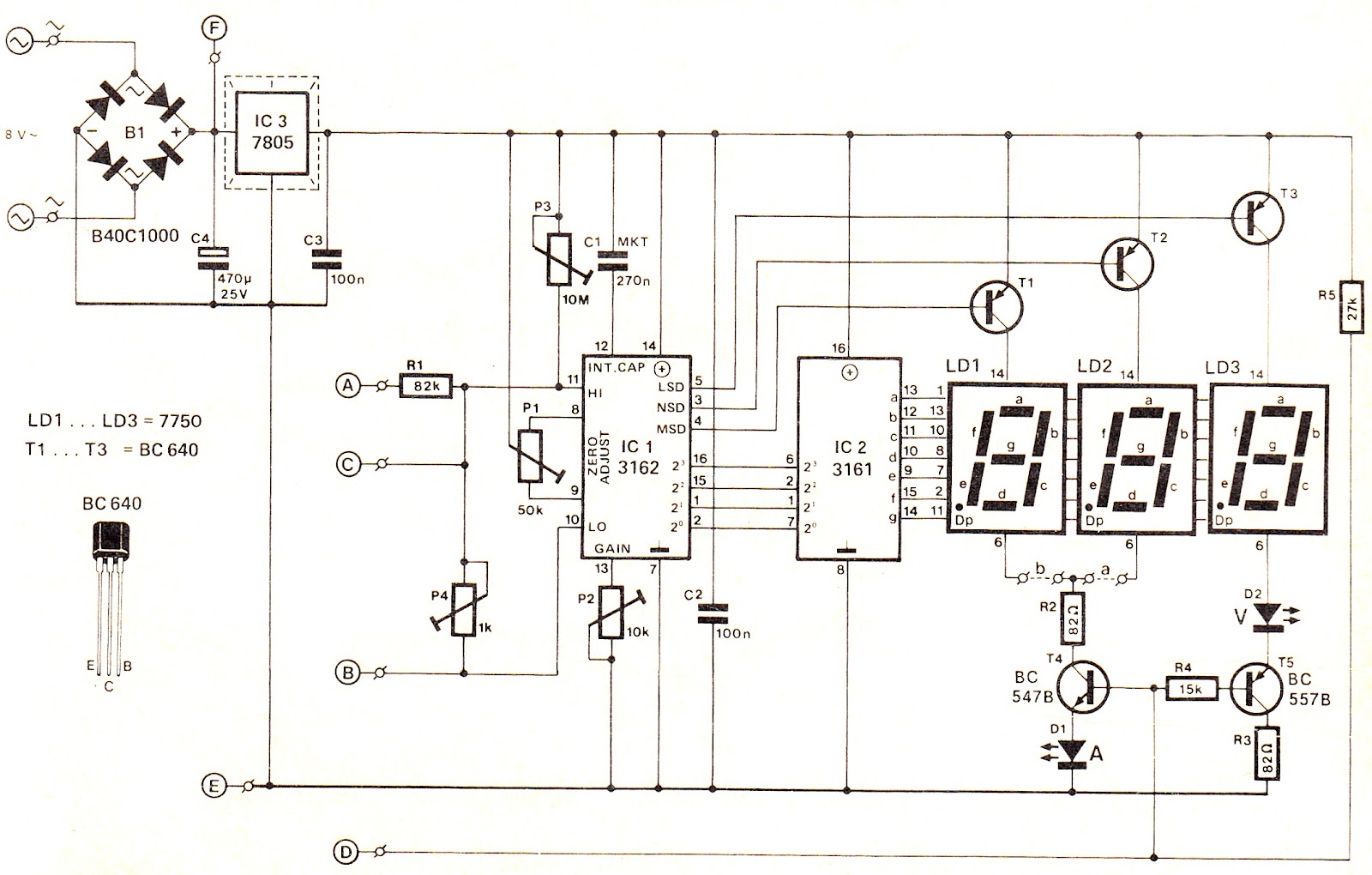
This voltage/current (V/I) display module is well-suited for integration into an existing DC power supply, providing precise readings of the set voltage or the current consumption of the load. The voltage measurement range features a decimal point indicator (LD3),...
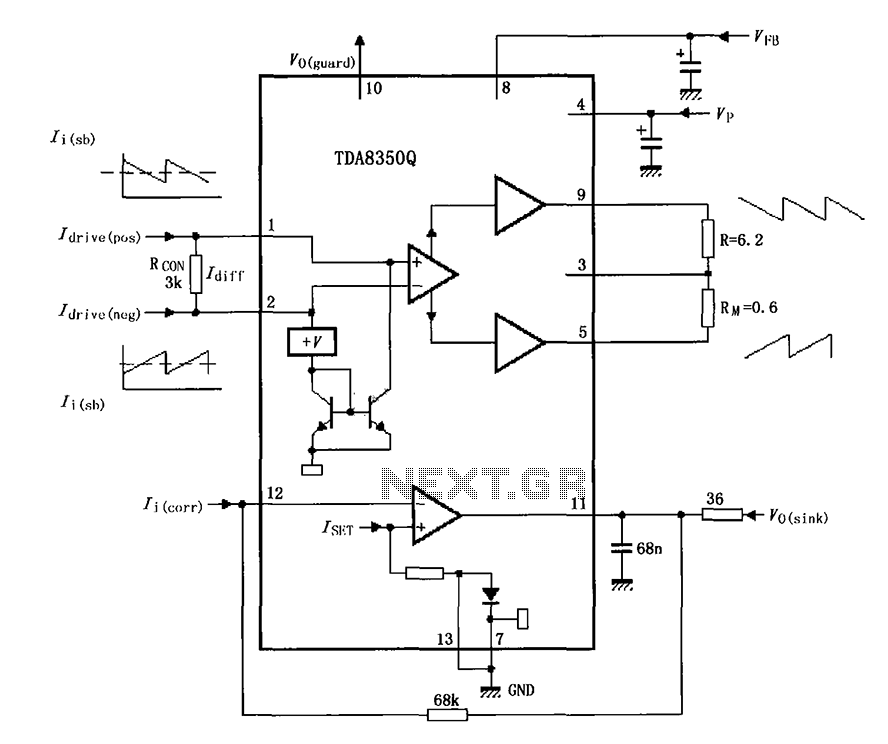
The TDA8350Q test circuit includes a push-pull amplifier configuration where the output terminal resistor serves as a dummy load for testing an alternative deflection coil. The TDA8350Q is a high-performance integrated circuit designed for use in television and display systems....
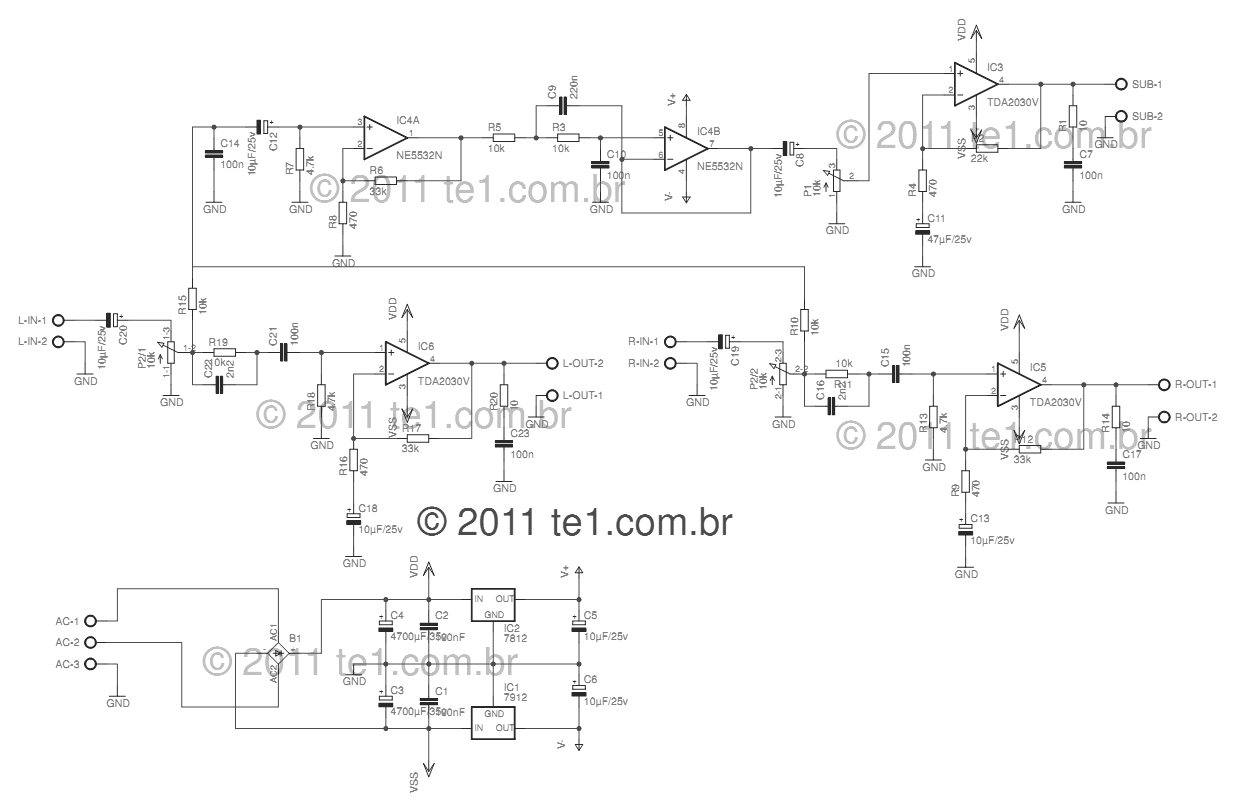
This circuit is a complete application for a 2.1 amplifier system, featuring two satellite speakers for TDA and one subwoofer. It is commonly used in commercial applications to enhance the audio output of computers using a stereo amplifier along...
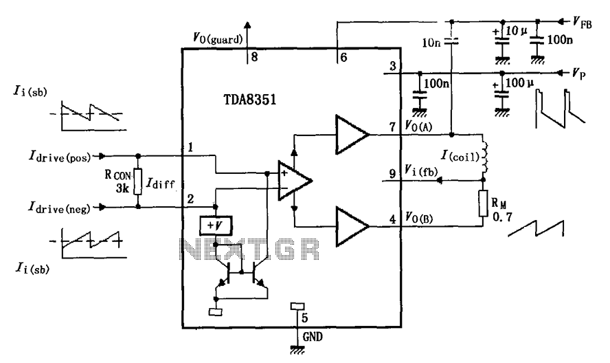
The figure illustrates the actual application circuit for the TDA8351/8356. In this circuit, a 50V voltage feedback (VFB) is connected in series with a 33-ohm resistor. Signals are input at pins 1 and 2, where pin 1 receives a...