
Ridiculously Simple AVR AM Radio Transmitter
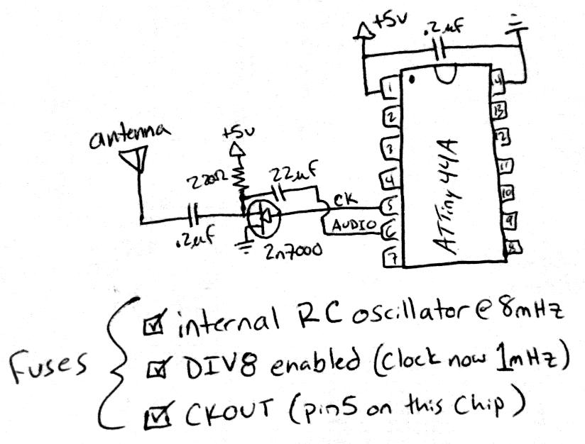
The circuit design for this transmitter/receiver pair centers around the ATTiny44A microcontroller, which serves as the heart of the system. The microcontroller's 8MHz RC oscillator provides a stable clock source that can be divided down to generate a 1MHz signal. This frequency is advantageous as it falls within the standard AM radio band, allowing for compatibility with common radio receivers.
The output from the CKOUT pin is initially a square wave, which, while visually appealing, lacks the power needed for effective transmission. To address this, the Class C amplifier stage using the 2N7000 MOSFET is employed. The MOSFET is configured to amplify the square wave signal. The drain of the MOSFET is connected to a 220-ohm resistor, which acts as a load and helps shape the output signal. The gate of the MOSFET is driven by the CKOUT output, allowing the square wave to control the MOSFET's switching.
To modulate the output signal, a microcontroller pin is used to apply a varying voltage to the drain of the MOSFET through a decoupling capacitor. This modulation technique enables the transmission of Morse code by rapidly turning the signal on and off, creating distinct dots and dashes. The simplicity of this design allows for easy implementation and testing, making it ideal for hobbyists and those new to radio transmission.
It is important to note that while this circuit demonstrates the principles of amateur radio transmission, there are legal limitations regarding power levels and frequency usage. Exceeding certain power thresholds can interfere with licensed broadcasters and may result in regulatory actions from the FCC. Therefore, caution should be exercised when using this circuit, particularly regarding the output power and frequency harmonics generated by the square wave signal.Create a rapid transmitter/receiver pair that anyone would have around their house. I decided that AM or FM radio would be good since everyone can receive that, and pondered how best to generate the necessary radio signal and modulate it appropriately. After a few LC oscillator designs, I thought about the RC oscillators built into most micro-controllers.
I grabbed an ATMEL AVR I had on hand (an ATTiny44A) and checked the datasheet. It had an 8MHz RC oscillator, which could be divided-down to 1MHz, and output on a CKOUT pin all configurable with a few hardware fuses! Note that commercial AM radio stations are between 0. 52 and 1. 61 MHz, so a 1MHz signal would be smack-dab in the middle of our radio dial! I had to build a prototype to see how well it would work. Once concern was that the RC oscillator wouldn`t be stable enough to produce reliable audio boy was I wrong!
The circuitry is textbook simple. Appropriately configured, the AVR generates 5V square waves from its CKOUT pin. Although a pretty shape, they`re not powerful enough on their own to be heard across a room, so I needed an amplifier stage. A class C amplifier provided by a 2n7000 is commonly done in the low power amateur radio (QRP) community, so I went with it.
A 2n7000 N-channel MOSFET with a 220-ohm resistor on the drain and the CKOUT directly into the gate did a fine job (I`ve used this design for 10MHz QRSS transmitters before), and I was able to modulate its amplitude by feeding the voltage from a MCU pin (turned on/off rapidly) through a decoupling capacitor into the drain of the MOSFET. I couldn`t have asked for a simpler result! This code sends a message in Morse code. It seems too easy! Applications are endless, as this is one heck of an easy way to send audio from a micro-controller to a radio, and possibly to a computer.
Morse code is easy, and since we have the ability to dynamically generate different audio frequencies and tones, data exchange is easy too! Nothing`s stopping you from adding the code to turn this into a RTTY (or Hellschreiber ) transmitter.
// designed for and tested with ATTiny44A #include
This means a 1 MHz transmitter, producing square waves, will generate tones on 1, 3, 5, 7 MHz, etc. Don`t do this with much power! Heck, you probably shouldn`t do it at all ;-) Scott Harden has had a lifelong passion for computer programming and electrical engineering, and recently has become interested in its relationship with biomolecular sciences. He has run a personal website since he was 15, which has changed names from HardenTechnologies. com, to KnightHacker. com, to ScottIsHot. com, to its current SWHarden. com. Scott has been in college for 10 years, with 3 more years to go. He has an AA in Biology (Valencia College), BS in Cell Biology (Union University), MS in Molecular Biology and Mic
🔗 External reference
Related Circuits
Sensitive FM Transmitter. Additional Notes: The default for the capacitors type is ceramic, preferably the NPO 1% type or equivalent. However, nothing critical is here; any type can be used. The sensitive FM transmitter circuit is designed to operate in...

In the event of a sudden power failure in an elevator, it is crucial for the duty officer in the distribution room to be alerted promptly to prevent panic among passengers trapped inside. The following describes a sound alarm...
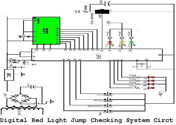
A digital red light jump checking system with an RF transmitter. This project allows for the tracking of vehicles that run red lights by capturing their license plate numbers and the time of the violation. The digital red light jump...
This radio receiver can operate with any of the following transistors: ZN414, MK484, or TA7642. The radio receiver circuit is designed to utilize a variety of transistors, specifically the ZN414, MK484, and TA7642, which are commonly used in low-power AM...

This is a transistor tester integrated into a circuit or printed circuit board (PCB). It is utilized when a project does not function correctly, allowing for the testing of electronic components. The transistor tester is a crucial tool in electronic...
This schematic represents a tone transmitter. When using sufficiently small resistor values, it generates a tone. A resistive microphone (such as a carbon microphone) can be placed in parallel with or replace the resistor, allowing modulation of the tone...