
DIY Function Generator
The circuit was constructed according to the schematic, with modifications made to replace the 1M resistor between the power supply and the square wave output with a 2M trimpot to achieve the correct waveform amplitude in relation to the sine and sawtooth waveforms. The construction utilized non-coppered perfboard, with preliminary markings made using fine-point Sharpie markers to plan the connections before assembly. The enclosure repurposed from an old 4-way data switch box measures 7.5" x 2.25" x 5" deep, with graphics created for the faceplate. A recycled rotary switch from an old parallel port A/B switch box was adapted for the frequency range control, requiring some internal adjustments to function correctly.
The circuit employs a single female BNC jack and a single 1/4" jack wired in parallel, along with three SPST switches to toggle between different waveforms. One switch is an on-center off-on type, serving as a "kill switch" to prevent waveforms from reaching the output jacks while keeping the unit powered. Although this homebrew function generator lacks the precision and features of commercial models, it remains adequate for hobbyist use. While the sine wave may not be entirely accurate when switching frequency ranges, a potentiometer has been incorporated to correct waveform offsets, ensuring usability and reasonable accuracy. This project is estimated to cost around $20.
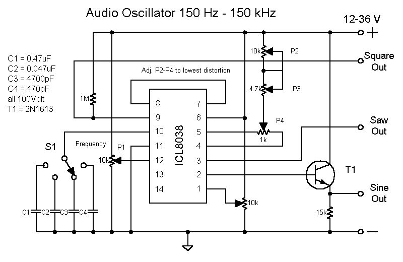
The ICL8038 function generator chip is a versatile and robust component capable of generating high-quality waveforms, making it suitable for various applications in electronics. Its ability to produce sine, square, and sawtooth waveforms simultaneously allows for a wide range of testing and experimentation in circuit design. The choice of a unipolar or bipolar power supply provides flexibility in power management, accommodating different circuit requirements.
The circuit design minimizes component count, which not only reduces cost but also simplifies troubleshooting and assembly. The use of trimpots for tuning allows for precise adjustments of waveform characteristics, enhancing the overall performance of the generator. Additionally, the implementation of a kill switch is a practical feature, enabling users to quickly silence the output without disconnecting power, which is particularly useful during testing phases.
The enclosure design, utilizing repurposed materials, reflects a sustainable approach to electronics projects, demonstrating how existing components can be creatively adapted for new uses. This not only reduces waste but also encourages resourcefulness among hobbyists. The careful planning and marking of connections on perfboard prior to assembly illustrate good practices in circuit construction, promoting accuracy and efficiency.
Overall, this function generator project exemplifies a balance between simplicity, functionality, and cost-effectiveness, making it an excellent choice for electronics enthusiasts looking to build a reliable waveform generator for various applications.The circuit is simple. It uses a single IC chip, the ICL8038 function generator chip which produces simultaneous sine, square and sawtooth wave forms. There are relatively few parts in the circuit - just two resistors, one transistor, five trimpots and the function generator chip.
The ICL8038 can operate on a unipolar power supply between 10 and 36 volts DC, and it can also be used with a bi-polar power supply. I built it per the schematic and it works, except I had to change the 1M resistor between the power supply and the square wave output to a 2M trimpot to get the waveform to function properly and be at the right amplitude in comparison with the sine and sawtooth waveforms. Check out the pictures below. This is the top of the circuit board. I used some non-coppered perfboard I had lying about to build the circuit on. Whenever I use perfboard, I like to mark up my perfboard with some fine point Sharpie markers and get all the connections worked out before I actually construct the circuit.
I find it easier to do it this way. Here is a view of the front. The enclosure comes from a defunct 4-way data switch box. I gutted it and created some graphics for the faceplate. It measures 7. 5"x2. 25"x5" deep. For the frequency range switch, I used a recycled rotary switch from an old parallel port A/B switch box. To make it work with this circuit, I had to disassemble it and rearrange the insides a little bit, but now it does exactly what I want it to.
(I know, I could have just bought a new rotary switch, but I had this switch lying around. ) Since I am using a single female BNC jack and a single 1/4" jack wired in parallel, I decided to use three SPST switches to switch between the different waveforms. One of the switches will be a on-center off-on type. I figure the middle position would make a nice "kill switch" which will prevent any waveforms from reaching the output jacks.
I like the idea, because if I don`t want any output, I can just flip that switch and leave the unit powered up. Of course, one could just use another rotary switch with a SPST switch that could act as a kill switch as well.
I used the SPST switches mainly because I had a bunch of them lying around waiting for a new home. This homebrew function generator isn`t as fancy or accurate as the ones that are on the market, but for a do-it-yourselfer hobbyist type, it`s adequate. I have found that the sine wave isn`t totally accurate when I switch between frequency ranges, but I have incorporated a pot which corrects any waveform offsets, so it still quite useable and pretty accurate.
Not too bad for a $20 project. 🔗 External reference
Related Circuits
A small audio test generator is highly effective for quickly tracing signals through audio equipment. Its primary function emphasizes speed over precision. Typically, a single sine-wave signal of approximately 1 kHz suffices, and distortion levels are not critically important....
Oscillation frequency 10Hz ~ 20MHz, 6 ranges. Analog output Sine, triangle, square wave (0 ~ 4Vp-p, Zo = 50Ω). TTL Output Clock (Duty: 50% fixed) positive negative pulse (variable pulse width). Operating system Show: oscillation frequency and operating mode...
This document presents a verified circuit diagram for a simple, interesting, and cost-effective electronic clapper (sound generator) circuit, along with a description of its functionality. The electronic clapper circuit is designed to activate sound generation through the detection of sound...
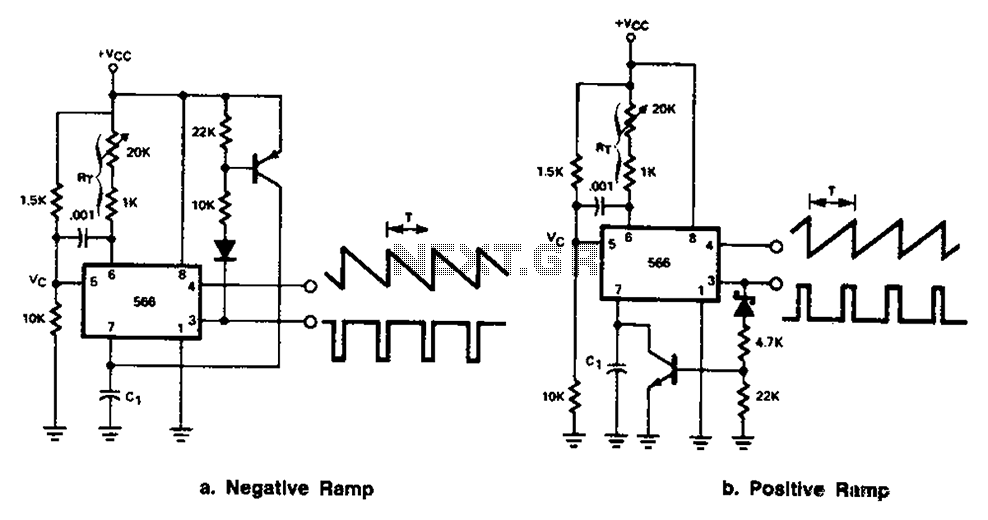
The 566 can be connected to either a positive or negative ramp generator. For a positive ramp generator, an external transistor is driven by the output pin 3. At the end of charging, C1 discharges quickly, allowing for immediate...

A monostable multivibrator (MMV) features one stable state and one quasi-stable state. The circuit remains in its stable state until an external triggering pulse prompts a transition to the quasi-stable state. After a designated time period T, the circuit...
A 555 timer operating in astable mode generates driving pulses, while two 4518 dual BCD (binary coded decimal) counters provide square waves. A TL081 operational amplifier functions as an output buffer-amplifier. Potentiometers R1 and R2 are utilized to control...