
Ramp generator circuit diagram

The 566 integrated circuit (IC) is a versatile component frequently used in applications requiring ramp signal generation. It can be configured to work with both positive and negative ramp generators, making it adaptable to various circuit designs. In a typical application involving a positive ramp generator, the 566's output pin 3 is utilized to drive an external transistor. This transistor acts as a switch that controls the charging and discharging of a capacitor, commonly designated as C1.
During the charging phase, the 566 generates a linear voltage ramp, which is applied to C1. The voltage across C1 increases gradually, creating a smooth ramp signal. Once the voltage reaches a predetermined level, the output pin 3 activates the external transistor, which rapidly discharges C1. This quick discharge is crucial as it allows the circuit to reset and prepare for the next charging cycle without significant delay.
The design of this circuit can be optimized by selecting appropriate values for C1 and the associated resistors, which determine the charging time constant and the ramp-up rate. Additionally, the choice of the external transistor influences the discharge speed, which is vital for high-frequency applications where rapid transitions are required. Overall, the 566 IC's ability to generate precise ramp signals makes it an essential component in various electronic applications, including waveform generators, timing circuits, and analog-to-digital converters. Circuit Description: The 566 can be connected to either positive or negative ramp generator. For positive ramp generator, the external transistor driven by the output pin 3, at the end of charging, quick to discharge C1, so you can immediately start charging again.
Related Circuits
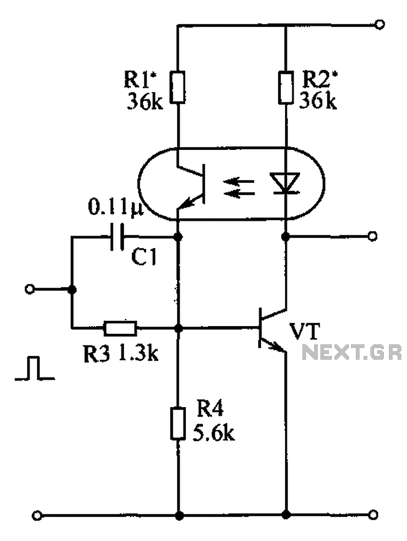
The bistable circuit and optocoupler transistor operate as illustrated in the accompanying figure. Initially, when the supply voltage is applied, the transistor VT is in the off state, resulting in a high output potential. Upon receiving a forward pulse...
The search coil, CI and C2, form a tuned circuit for the oscillator, which is tuned near the center of the broadcast band. Tune a portable radio to a station near the middle of the band, then adjust C2...
This circuit is straightforward. The initial 555 timer prevents the second timer from being activated while the first is operational. Drive the circuit with a simple 12-volt power supply. The circuit utilizes two 555 timer integrated circuits (ICs) configured in...
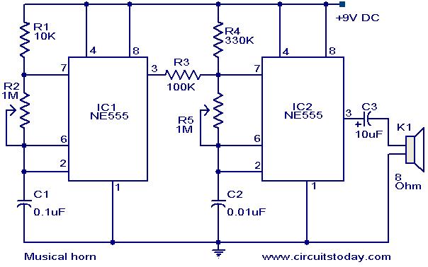
This document outlines a straightforward circuit diagram for a musical horn utilizing two NE555 integrated circuits (ICs). Both ICs are configured as astable multivibrators. The output from the first multivibrator is connected to the discharge pin (pin 7) of...
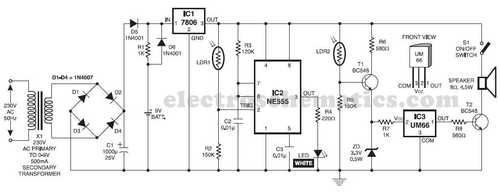
This musical light alarm circuit is very simple and uses only seven components, including a light-dependent resistor (LDR) and a 3.6V battery or three 1.2V rechargeable batteries. The well-known UM66 is utilized as the sound generator, providing a pleasant...
This is an enhanced infrared (IR) remote control extender circuit. It features high noise immunity, resistance to ambient and reflected light, and an extended range of approximately 7 meters from the remote control to the extender circuit. It is...