
Electronics Clapper (sound generator) and description
 and description")
The electronic clapper circuit is designed to activate sound generation through the detection of sound waves, specifically clapping. The primary components of this circuit typically include a microphone, an amplifier, a rectifier, and a sound output device such as a speaker or buzzer.
The microphone serves as the input transducer, converting sound waves from claps into an electrical signal. This signal is then amplified by an operational amplifier (op-amp) to ensure that it reaches a sufficient level for processing. The output from the amplifier is fed into a rectifier circuit, which converts the AC signal generated by the microphone into a DC signal.
Once rectified, the DC signal is used to trigger a relay or transistor, which subsequently activates the sound output device. The sound output device can be a simple piezo buzzer or a small speaker, depending on the desired sound quality and volume.
To improve performance, the circuit may also include additional components such as capacitors for filtering, resistors for biasing, and potentiometers for adjusting sensitivity. The design can be further enhanced by incorporating a microcontroller for more complex sound patterns or additional features like adjustable sensitivity and sound duration.
This circuit is ideal for various applications, including novelty items, alarms, or interactive toys, due to its straightforward design and low cost. Proper attention to component selection and circuit layout will ensure reliable operation and longevity of the electronic clapper system.Here is verified circuit of simple, interesting and inexpensive electronics clapper (sound generator) circuit diagram with description of electronics clapper. 🔗 External reference
Related Circuits
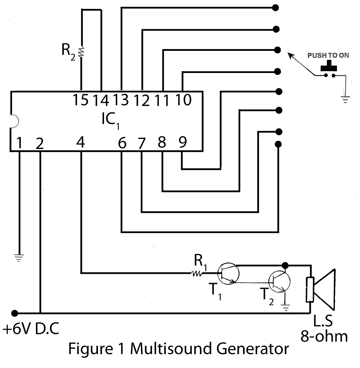
The multisound generator is an intriguing project within the alarm system series. This generator produces eight different types of sounds, and it includes a circuit diagram for various electronic projects. The multisound generator circuit is designed to create a variety...
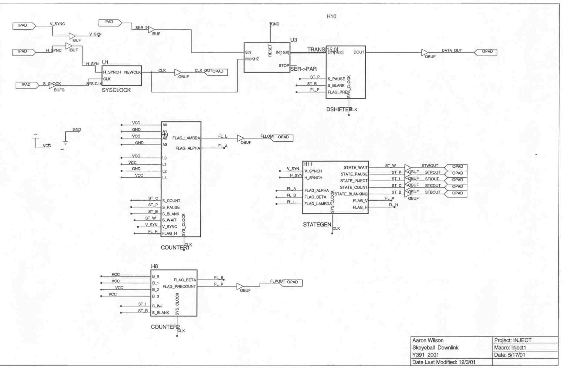
The Skeyeball project is an ongoing initiative within the Indiana University System Design Methods Laboratory, aimed at providing graduate and undergraduate students with opportunities to engage in embedded system design and implement various projects. The downlink segment of the...
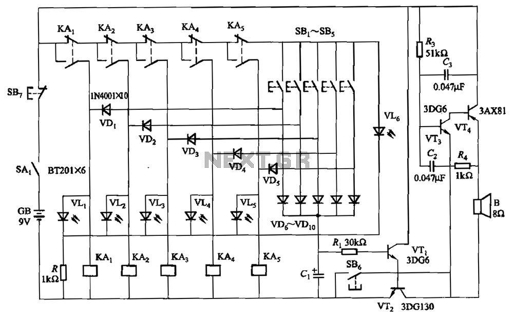
A relay-style circuit designed for a five electronic responder group. This circuit features self-locking capabilities, sound and light displays, time monitoring, and additional functions. The circuit includes a monitoring time button operated by the moderator. When this button is...
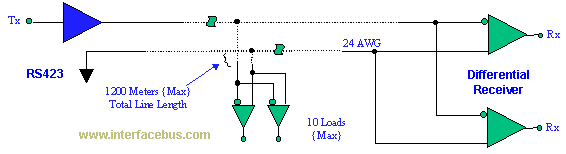
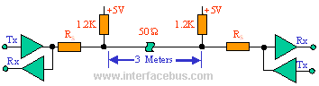
The EIA/TIA-423 Unbalanced (Single-Ended) interface specifies a single, unidirectional driver with multiple receivers (up to 10). It outlines the electrical characteristics of the unbalanced voltage digital interface circuit, typically implemented in integrated circuit technology, which can be used for...
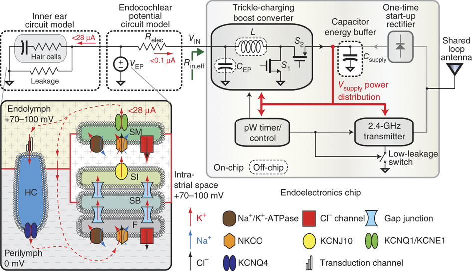
To generate and maintain the endocochlear potential (EP), perilymphatic potassium ions (K+) enter fibrocytes (F) through the Na+/K+-ATPase and Na-K-Cl cotransporter. Gap junction networks connect fibrocytes to strial basal (SB) and intermediate (SI) cells, allowing ions to enter the...
The IEEE-1284 bus specifies a parallel printer bus with data transfer speeds exceeding 1 MBps. It defines a point-to-point asynchronous bi-directional interface. Devices can be either 1284 compatible (older parallel port devices) or 1284 compliant. The maximum recommended length...