
DIY Infrared Radar System
The do-it-yourself radar system utilizing the PIC18F452 microcontroller presents an engaging project for electronics enthusiasts. The PIC18F452 is a versatile microcontroller from Microchip Technology, equipped with a 14-bit instruction set architecture, 32 general-purpose I/O pins, and integrated peripherals, making it ideal for various applications, including radar systems.
The radar system operates by emitting a radio frequency signal and measuring the time it takes for the signal to reflect off an object and return to the receiver. The PIC18F452 microcontroller is programmed to control the timing and processing of the received signals, allowing it to calculate the distance to the object based on the time delay.
Key components of the radar system include an RF transmitter and receiver, which may be implemented using antennas designed for the specific frequency band of operation. The microcontroller interfaces with these components through its GPIO pins, utilizing PWM (Pulse Width Modulation) for signal generation and ADC (Analog-to-Digital Conversion) for processing the received signals.
The circuit may also include additional elements such as a display module (e.g., LCD or OLED) to visualize the distance measurements, and a power supply circuit to ensure stable operation of the microcontroller and RF components. Proper filtering and amplification circuits are essential to enhance signal clarity and reduce noise interference.
Overall, this project not only demonstrates practical applications of microcontroller programming and RF communication but also provides valuable insights into radar technology, making it a comprehensive learning experience for hobbyists and students in the field of electronics.Chris has a great article about a do-it-yourself radar system build with PIC18F452. It s a great hobby project although the schematic.. 🔗 External reference
Related Circuits
Long-distance infrared transmitter circuit diagram. This simple circuit offers a considerable range by utilizing three infrared transmitting LEDs (IR1 through IR3) in series to enhance the radiated power. To further improve directivity and power density, the IR LEDs can...
Using this low cost project, one can reproduce audio from a TV without disturbing anyone. It does not use any wire between the TV and headphones. Instead of a pair of wires, it uses invisible infrared light to transmit...
This is a remote-controlled land rover that can be operated using a cell phone. This allows the user to move the land rover by sending various commands from their device. The rover can be controlled from virtually anywhere in...
The TTY and the detector-transmitter unit are connected to separate phone jacks on the same line. When the ring sensor detects an incoming phone call, it activates the transmitter, which sends an RF signal to the receiver in the...
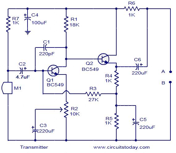
The circuit schematic illustrates a simple audio surveillance system in which the transmitter captures sound from one location, while the receiver reproduces it at another location. Both the transmitter and receiver are connected by a single wire, which carries...
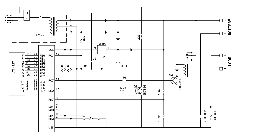
The PIC16F870 keeps track of battery voltage as well as both charging and discharging currents. It also drives the 4 digit display and switches the AC and load relays. The basic operation is as follows: While AC power is...