
Personal Silent Alarm System Diagram Project
The circuit design for the ring detector begins with the connection to the telephone line. The peak detector circuit is crucial for accurately capturing the ringing signal. It consists of a diode and a capacitor, where the diode rectifies the incoming AC signal and the capacitor holds the peak voltage for the specified duration. The choice of components must ensure that the circuit can handle the high voltages present during ringing while providing adequate protection against transients.
The transmitter section utilizes the RT300T module, which is designed for low-power applications. The RF signal is generated when the ring detector activates the transmitter, sending a coded signal to the receiver. The receiver, integrated within the pager device, decodes the signal and activates the motor driver circuitry, which in turn powers the vibrating motor.
The motor driver circuit typically employs a transistor or a relay to switch the motor on and off based on the received signal. The design must consider the current and voltage ratings of the motor to ensure reliable operation. Additionally, the use of a debounce circuit may be necessary to prevent false triggering due to noise in the signal.
Overall, the circuit must be designed with attention to component selection, layout, and protection mechanisms to ensure reliable and consistent performance across different telephone line standards. The incorporation of surge protection and the careful design of the interfacing circuitry play vital roles in maintaining the integrity and functionality of the system.The TTY and the detector-transmitter unit are connected to separate phone jacks on the same line. When the ring sensor detects an incoming phone call, it activates the transmitter, which sends an RF signal to the receiver in the pager device. The receiver activates intermediate circuitry which drives the vibrating motor and thus alerts the user to
the incoming call. In this section we describe the design and implementation of the ring detector and its connection to the transmitter. We also describe the circuitry in the pager that connects the receiver to the vibrating motor. We required an understanding of the signals and standards used in telephone communication in order to build the interface between the telephone line and the transmitter.
Figure 2. 2 shows the signals on a silent and a ringing telephone line. When the line is silent, a DC voltage of Vl = 48 V is present. During ringing this voltage is superposed with a sine wave of considerably large amplitude. Often the ringing amplitude is 80 Vrms, which gives a peak voltage of Vp = 48 V +/- 1. 4 * 80 V = {+160 V; -64 V}. Not all telephone companies use the same standard for their ring signals, so the amplitude and frequency can vary over a wide range. A telephone line in use has a small DC voltage of approximately Vl = 4 V with a superposed current signal (from a voice, fax, or modem) which corresponds to a voltage change of up to 2 V in amplitude.
In order to make our product compatible to every telephone ring standard, we used the amplitude of the line voltage to distinguish a ringing line from all other possible telephone line states. All telephone standards have one property in common: The peak voltage of a ringing line is significantly higher than the DC voltage for a silent line or a line in use.
Using this approach the frequency of the ringing signal does not play a role in detecting a ring signal. Figure 2. 3 shows the block diagram of the ring detector. The incoming voltage Vl comes from the telephone line and goes into a peak detector where the peak voltage is stored for 0.
1 seconds. This duration is double the period of the lowest possible ringing frequency of 20Hz. The voltage Vp is the output of the peak detector. Vp is 48 V for a silent line, greater than 48 V for a ringing line, and much less than 48 V when the line is in use. is about 2 V for the silent line, greater than 2 V for a ringing line, and much less than 2 V when the line is in use.
Because of the inductance in the telephone line, high voltage peaks can occur if the current in the line changes rapidly. Such current changes can be caused by dialing, unplugging phones, driving mechanical ringers, and so forth.
To protect our circuit from these undesirable high voltages, we implemented surge protection in our circuit. A purchased transmitter-receiver pair, RT300T & RF300, was used to send an alert on detection of an incoming call or a ringing doorbell.
The vendor for the pair was Vistect Inc. , P. O. Box 14156 Fremont, CA, 94539, (510) 651-1425. The transmitter operates at 318 MHz and provides up to three channels. According to the specifications given in its data sheet its transmission range is about 100 m. A security code can be set in the transmitter and the receiver to provide privacy and to prevent interference with other transmitter units using the same frequency. The transmitter was packaged as a small hand-held device in a plastic case with two buttons to trigger either one or both of the channels.
It was powered by a 12-V battery. In order to interface the transmitter to other circuitry, we bypassed the buttons with PNP transistors. Figure 2. 5 shows this configuration in a simplified circuit diagram of our modified transmitter. With this modification, the transmission can be triggered by causing a small current (from 0. 1 to 5 mA) to flow from the base of the PNP transistors to ground. While testing, we supplied this current 🔗 External reference
Related Circuits

This circuit differs from the standard 555 oscillator circuit by placing the LED in the capacitor reset line (pin 7). This configuration reduces overall current and prevents high peak LED current from draining the battery. The forward voltage drop...
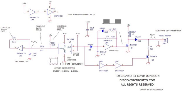
A loud sweeping siren-type audio sound generator powered by 3V. The circuit utilizes an LTC1799 precision frequency generator from Linear Technology and a 74HC14 hex Schmitt trigger from Texas Instruments to perform various functions. One section is configured as...
To comprehend the interconnections between the following circuits, it is essential to first review the concept chapter. It is at the discretion of the user to select one or two of these circuits for personal development. The discussion begins...
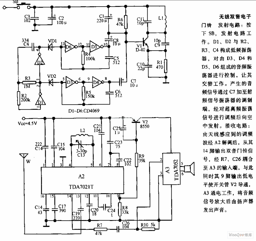
The transmitter circuit is activated by pressing the SB button. Components D1, D2, R2, R3, and C4 form a low-frequency oscillator that controls an audio oscillator made up of D3, D4, D5, and D6, allowing them to operate alternately....
This schematic diagram illustrates a water level sensor, detector, and monitor circuit. An alarm is also integrated into this circuit. It is designed to detect any fluid with a resistance below 900K ohms. The water level sensor circuit typically employs conductive...
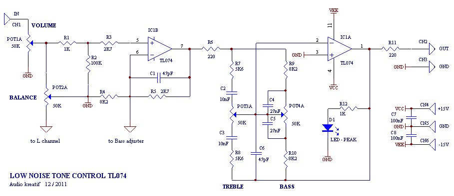
A tone control or pre-amplifier is an amplifier circuit that enhances audio signals. It is important to understand the characteristics, advantages, and disadvantages of various amplifier equipment, as the performance of different amplifiers may not show significant differences. The...