
DIY kinetic energy harvester

The project involves creating a kinetic energy harvester that converts mechanical energy from motion into electrical energy through electromagnetic induction. The fundamental principle is based on Faraday's law of electromagnetic induction, which states that a change in magnetic flux through a coil induces an electromotive force (EMF) in the coil.
To begin, a suitable framework for the harvester must be designed, which could include a pendulum or a vibrating mass mechanism. The choice of the mechanical system will depend on the specific application and the type of kinetic energy available, such as from walking, machinery vibrations, or environmental movements.
The core component of the electromagnetic method will be a coil of wire, typically made from copper due to its high conductivity. This coil will be positioned in close proximity to a magnet. As the pendulum or vibrating mass moves, it will cause the magnet to move relative to the coil, resulting in a change in magnetic flux and thus generating an electrical current.
The circuit design should include a rectifier to convert the generated AC voltage to DC, which can then be utilized for charging batteries or powering low-energy devices. A capacitor can be integrated into the circuit to smooth out the voltage output and store energy for use when the harvester is not generating power.
Additional components may include a voltage regulator to ensure a stable output voltage and a microcontroller for monitoring and controlling the energy harvesting process. Depending on the application, energy management systems can be implemented to optimize the efficiency of energy storage and usage.
In summary, the design of the DIY kinetic energy harvester will involve careful selection of materials and components to effectively capture kinetic energy and convert it into usable electrical energy through electromagnetic induction.A DIY kinetic energy harvester and wish to use the electromagnetic method to generate electricity. So far I know the following materials that I`m going to use: 🔗 External reference
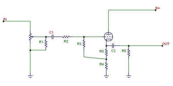
Related Circuits
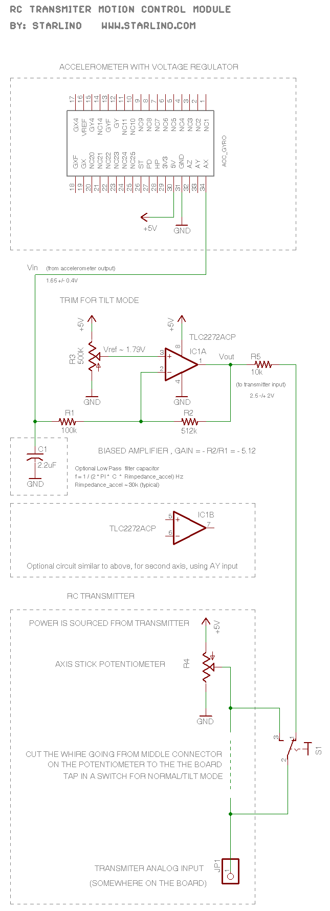
The RC transmitter utilizes a potentiometer for each axis, functioning as a voltage divider that outputs a voltage of 0.5V, with the middle position corresponding to 2.5V. This voltage is sent to the analog input, which is converted into...
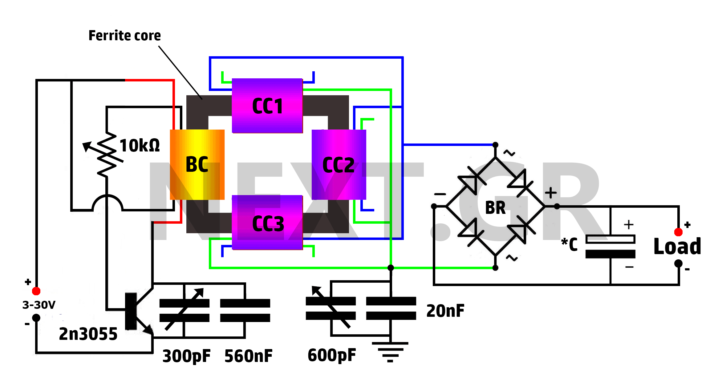
This is a Tesla/joule thief hybrid circuit that its inventor claims can produce 90 times the input power. The circuit can be self-looped and can provide 1050W of power, with only 11.6W looping back to supply the joule thief....
.jpg)
This is a two-phase hybrid stepping motor with a dynamic voltage range of 12 to 48V and a maximum current rating of less than 5A. The motor has an outer diameter ranging from 35 to 86 mm. The drive...
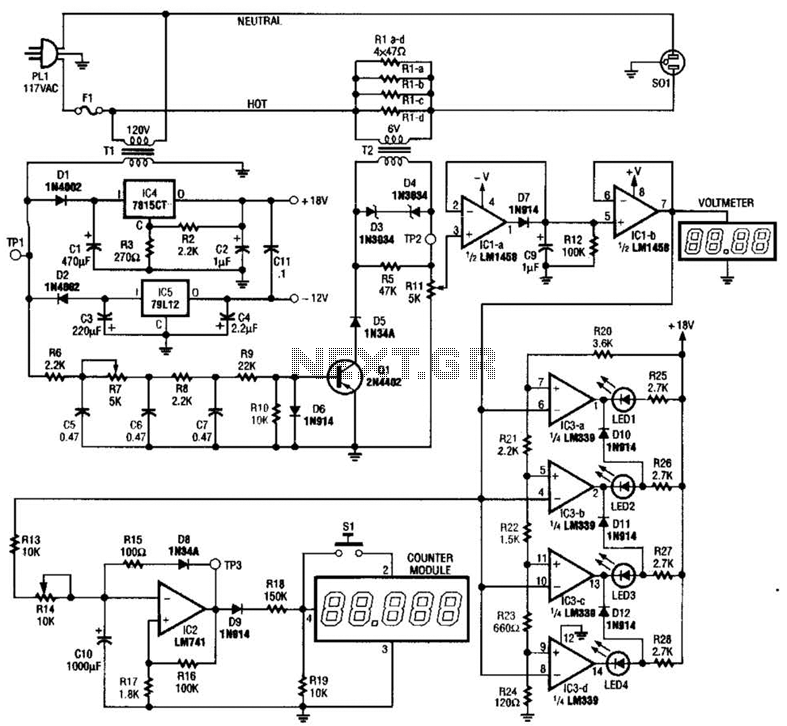
The ECM circuit comprises four sections, as illustrated in the block diagram. A power converter generates a voltage that correlates with the actual real power consumed by the load. This voltage supplies both a bar graph and a voltage-to-pulse...
There is nothing wrong with that setup in my opinion. An older Peltor FMT15 amplifier is used in a Golf, which works well for two Peltor headsets. The issue arises when mixing Peltor and Terraphone headsets/amps. All three of...
By sufficiently lowering the output impedance of a circuit and supplying enough current to drive cables, it avoids the issues faced by passive designs. This approach seems to address many of the inherent problems in both active and passive...