
diy tube buffered passive preamp
This situation leaves a couple of viable alternatives: the first is to utilize an op-amp that is stable at unity gain. However, op-amps tend to share the same audio quality issues as existing monolithic buffers, and the most effective op-amps are typically not stable at unity gain, thereby turning the design into an active preamp. The two remaining options are both promising: a discrete solid-state design or a tube design, such as a cathode follower. For this project, a cathode follower was selected. Despite its negative reputation, the cathode follower is frequently employed and effectively reduces the output impedance of a circuit, often performing better than its reputation suggests.
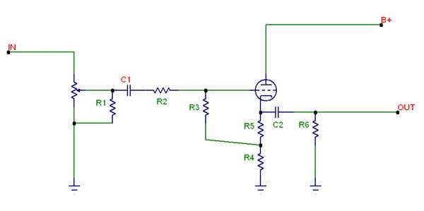
Currently, this project is in its initial stages, consisting of a circuit and a printed circuit board (PCB) design. Further developments will be shared if the project progresses to the construction phase. The basic schematic is derived from the Morgan Jones book, with the addition of resistor R1 for safety. This circuit can accommodate various tubes, including commonly used audio tubes like the 12AX7, 6DJ8, and 6SN7. The PCB was designed around the 9-pin miniature tube variety, specifically because several 6922 and 7308 tubes are available for use. These tubes are dual triodes, allowing a single tube to function as a stereo buffer.
The design files for the PCB are available for download, licensed under a Creative Commons license for personal, non-commercial use, with proper credit to the original designer. It is distributed with the hope of being useful, but without any warranty, including implied warranties of merchantability or fitness for a particular purpose. Caution is advised, as this design may involve lethal voltages, and should not be attempted without sufficient experience. Software from ExpressPCB is required for board production, with a cost of $51 for three boards. The design has not yet been constructed or prototyped, and users are encouraged to conduct thorough checks for errors, as inaccuracies may exist. The schematic and PCB do not include part values, as the board is designed for general use with multiple tubes, requiring users to determine the appropriate values based on their specific tube selection. The resistors are sized for 2.
The circuit design integrates a cathode follower configuration, which is known for its ability to provide high input impedance and low output impedance, making it suitable for driving loads such as long cable runs. The choice of tubes, specifically the 6922 and 7308, allows for enhanced audio fidelity due to their dual triode structure, which can effectively amplify and buffer audio signals with minimal distortion. The circuit layout must consider the power supply requirements for the tubes, ensuring that appropriate high-voltage and heater supply circuits are implemented to maintain stable operation.
When designing the PCB, attention must be given to trace widths and spacing to handle the required voltages safely. Additionally, the layout should minimize signal path lengths to reduce noise and interference. The inclusion of bypass capacitors near the power supply pins of the tubes can help stabilize the voltage and improve transient response.
Overall, this design represents a thoughtful approach to creating a tube-based audio buffer that capitalizes on the advantages of cathode follower circuits while addressing common pitfalls associated with both active and passive designs.By sufficiently lowering output impedence of a circuit and supplying enough current to drive cables, it does not suffer the same problems as passive designs. As such, it seems to solve the many of the problems inherent in both active and passive preamps without causing too many additional problems of is own.
The problem that I encountered in doing such a build from the Stereophile article is that not only is the monolithic buffer used there not readilly available, but the successor to it is also not available (they are available on the NOS market, however, if one is really interested. ) Further, of the currently available buffer chips, all of them (like the Burr Brown buf634 or the Intersil HA3-5002) seem to have something about them that make them poor choices for this type of projetct - prmarily that they just don`t sound that good.
This leaves a couple of additional options: The first is to use an opamp that is stable at unity gain. Opamps, however, suffer from the same problems as existing monolithic buffers (that they sound bad). Further, the best opamps are generally not stable at unity gain anyway, and thus, this would become an active preamp.
The two remaining options, however, are both good. These are to use a discrete solid state design, or to use a tube design like a cathode follower. For this project I chose to use the cathode follower. Cathode followers are much maligned, but at the same time they crop up in a lot of places. Despite the bad press, they do a good job of lowering the output impedence of a circuit, and really don`t sound as bad as their reputation suggests. As has been said elsewhere, you don`t listen to the reputation. This project is just getting started, so for now it is only a circuit, and a PCB design. When, and if, it gets built, I`ll post more. For now, here is the basic schematic. This is really just the circuit from the Morgan Jones book with the addition of R1 for safety. The same circuit can be used for a plethora of tubes, including some commonly used audio tubes as the 12AX7, 6DJ8, and the 6SN7.
I decided to design a printed circuit board (PCB) around the 9 pin miniature tube variety. This was mostly because I happen to have several 6922`s and several 7308`s around, and I thought I might put them to good use. These tubes are dual triodes which means that a single tube can be used as a stereo buffer. You can download the files to have these boards made from here. (notice that this design is copyrighted and hereby licensed under a creative commons license. It may be used and redistributed for personal, non-commercial, purposes, and you must always credit the original designer.
This design is distributed in the hope that it will be useful, but WITHOUT ANY WARRANTY; without even the implied warranty of MERCHANTABILITY or FITNESS FOR A PARTICULAR PURPOSE. Indeed, this design may use lethal voltages. Do not try to build it without sufficient experience to deal with them. ) You will need software from ExpressPCB for the board. This company will produce 3 boards for $51. This design has not been built of protyped. You should do a thorough check for errors on your own as I assume no responsibility for mistakes - and there most assuredly are a few.
Anyway, you`ll notice that the schematic and the PCB do not contain parts values. This is because the PCB is a general purpose board and can be used with a nuimber of tubes that will change these values. What this means is that you will need to figure them out yourself. The resistors are sized for 2 🔗 External reference
Related Circuits
In recent years, following CD's introduction, vinyl recordings have almost disappeared. Nevertheless, a phono preamplifier is still useful for listening to old vinyl discs from a well-preserved collection. This simple but efficient circuit devised for cheap moving-magnet cartridges can...
Recently, a music synthesizer has been constructed using vacuum tubes. Although designed primarily as a percussion synthesizer, it can also be controlled via a keyboard or a MIDI to CV converter. The initial module developed is a dual voltage-controlled...
The 12AX7 is currently the most widely used preamp tube for electric guitar amplification, with an extensive selection of contemporary production options available. This comparison aims to provide guitar players with a reference point to identify the most suitable...
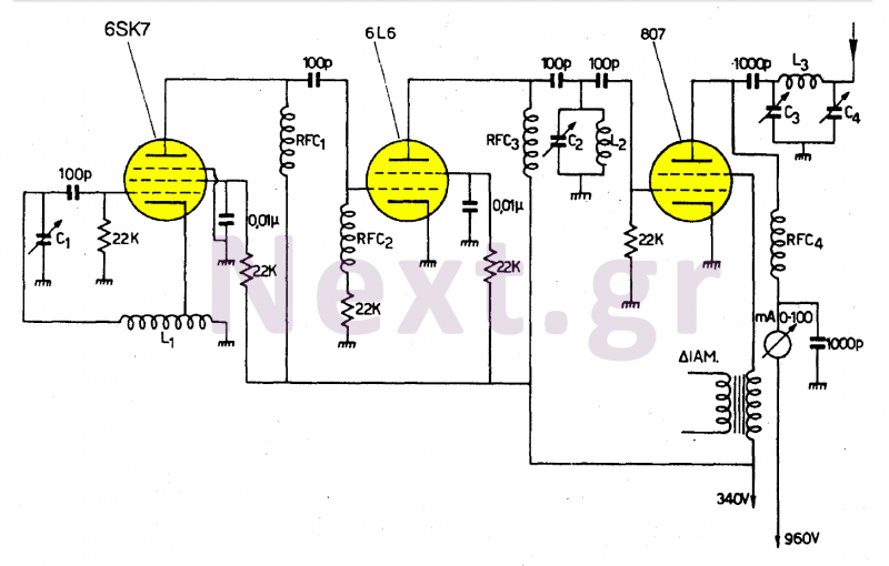
This transmitter operates in the shortwave range from 6 MHz to 22 MHz. Coil L1 serves as the shortwave oscillating coil for the 6SA7 vacuum tube and is commercially available. Capacitor C1 is a variable capacitor with a capacitance...
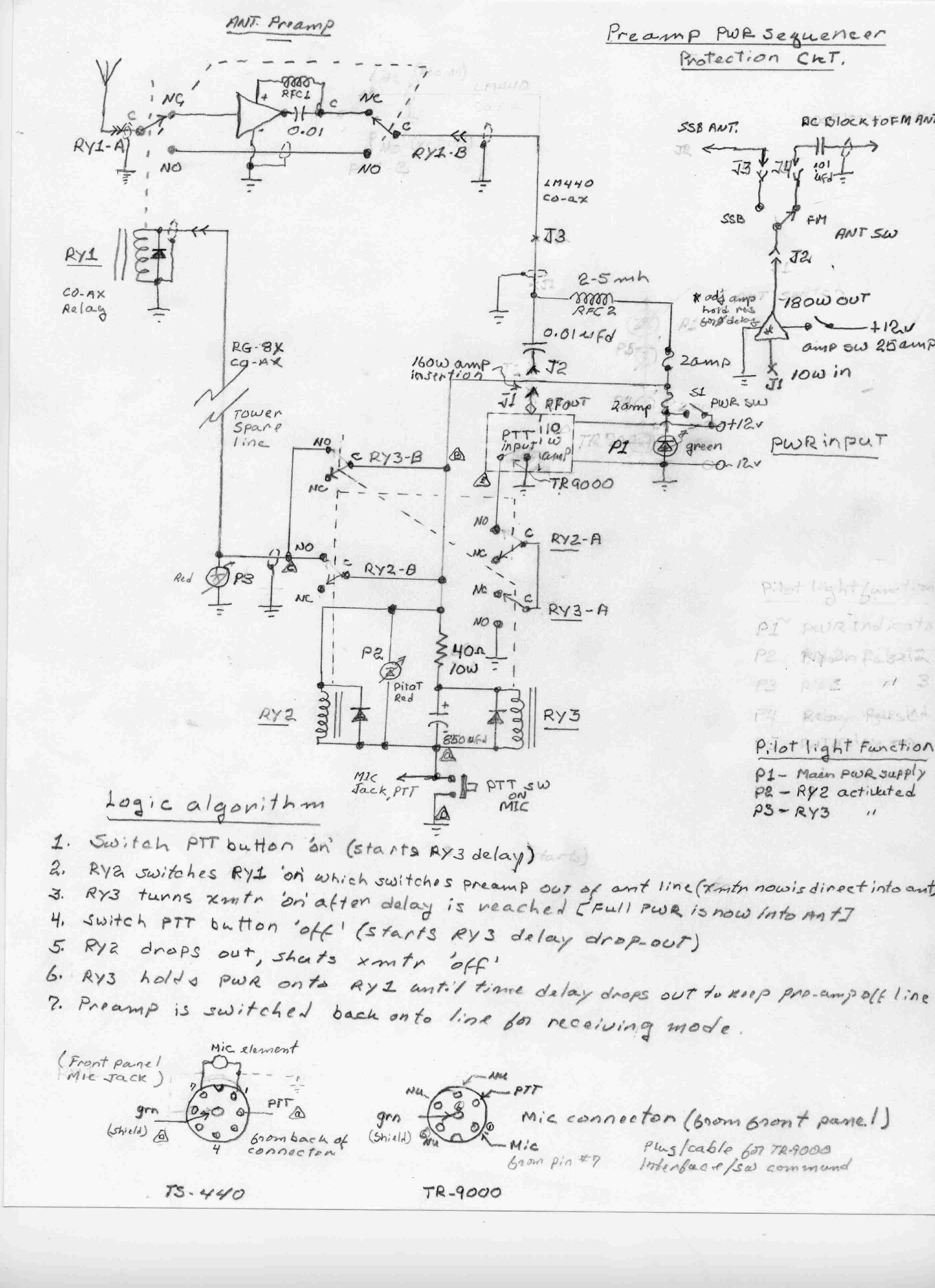
While operating a two-meter single sideband (SSB) from the Benson area, it was determined that the local terrain and the limited height of a homemade six-element Yagi antenna necessitated the incorporation of a high-gain antenna pre-amplifier at its termination...
To omit the balance control when using separate potentiometers for the volume controls, refer to the balance control notes on the 7-tube output amplifier page. A schematic was utilized to build a modified version with separate bass and treble...