
Energy Consumption Monitor Circuit

The ECM circuit is designed to monitor and display power consumption in a clear and efficient manner. The power converter is a critical component that transforms the electrical characteristics of the load into a usable voltage signal. This voltage is typically derived from a current transformer or a shunt resistor, ensuring accurate representation of the real power consumed.
The bar graph serves as a visual representation of power usage, allowing users to quickly assess the load's energy consumption without needing to interpret numerical data. It is typically composed of a series of LEDs or a liquid crystal display (LCD) that lights up in proportion to the power consumed.
The voltage-to-pulse converter is essential for translating the analog voltage signal into a digital format that can be processed by the counter module. This converter operates by generating a pulse train where the frequency of the pulses is directly proportional to the input voltage, effectively encoding the power consumption into a frequency signal.
The counter module, often integrated with a microcontroller or a digital signal processor, counts the incoming pulses over a defined time interval. This count is then converted into a cost estimate based on predefined rates for energy consumption. The display can be a simple numeric readout or a more complex graphical interface, depending on the design requirements.
In summary, the ECM circuit provides a comprehensive solution for monitoring power consumption, converting it into useful visual and numerical data, and facilitating cost analysis for energy usage in various applications. Its modular design allows for flexibility and scalability in different environments, making it suitable for residential, commercial, or industrial applications. The ECM circuit consists of four sections, as shown in the block diagram. A power converter generates a voltage that is proportional to the true of real power consumed by the load. That voltage feeds both a bargraph and a voltage-to-pulse converter. The bargraph gives an approximate indication of the amount of power used, and the voltage-to-pulse converter produces a pulse whose frequency is proportional to the power.
The pulse triggers the counter module, which displays the cost of powering the monitored load.
Related Circuits
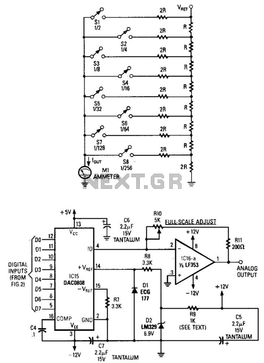
Figure A illustrates an R/2R resistor ladder. Each closed switch increases the current flow. A basic channel A/D converter is depicted in Figure B. The voltage reference (D2) is shared across all channels, although the value of the dropping...
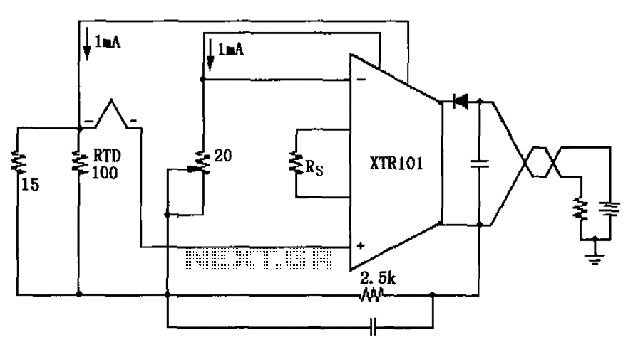
The circuit utilizes a type J RTD (Resistance Temperature Detector), where the resistance value is directly related to the temperature. Calibration of the zero point is facilitated by a 20-ohm adjustment potentiometer as specified by the manufacturer. The schematic features...
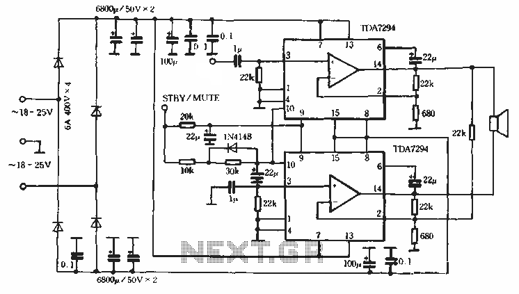
Europe's leading SGS-THOMSON STMicroelectronics recently introduced a new power integrated amplifier, the TDA7294, to the Chinese mainland market. This amplifier, characterized by a cold and hard tone, is particularly suited for Hi-Fi applications such as home theaters and active...
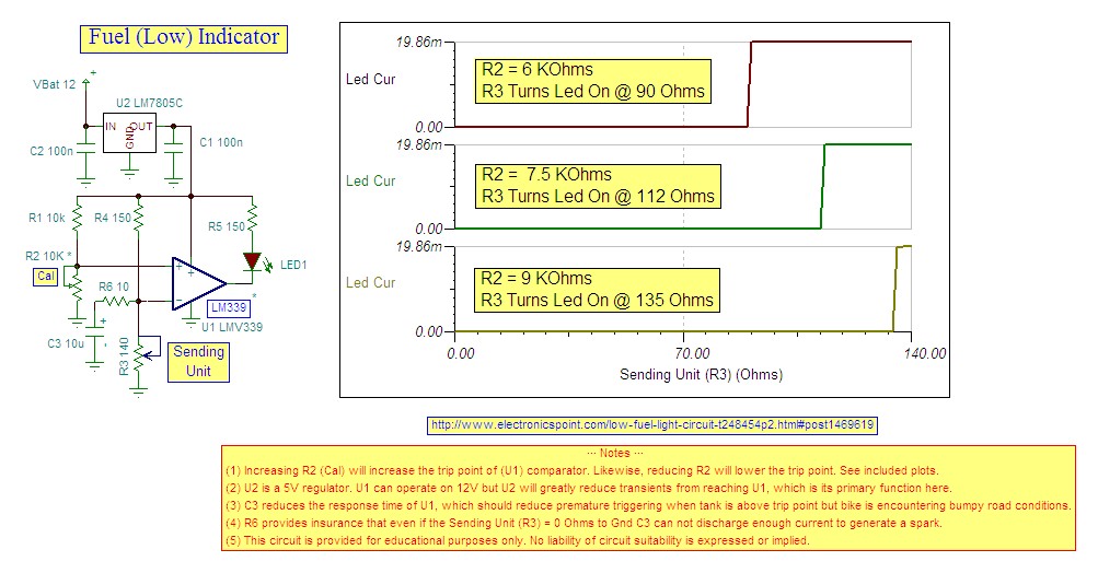
Research indicates that the sender will register a resistance of 100 ohms when the fuel tank is empty, making a trigger reading of 80 ohms optimal. The fuel gauge sender is a critical component in monitoring the fuel level within...
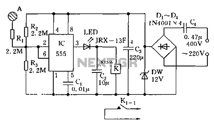
The touch sensor switch circuit diagram features a step-down rectifier circuit, a 555 timer, and flip-flops. When a hand touches the metal sheet A, the sensor signal activates the internal comparator of the 555 timer, setting the output to...
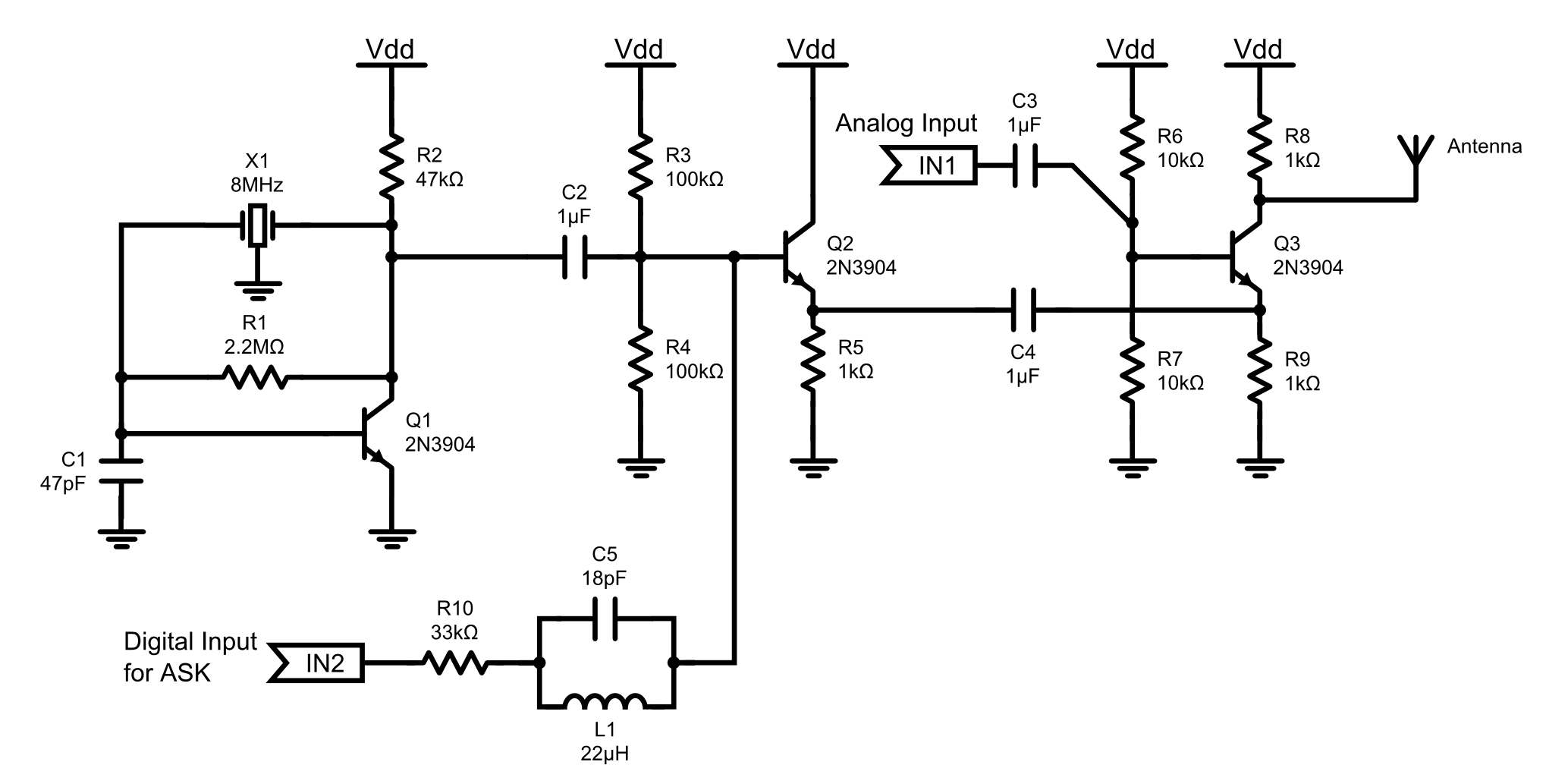
This is an 8MHz amplitude modulated (AM) radio transmitter designed primarily for practical applications and as an educational exercise in electronics. The objective was to create a simple radio transceiver that could be used in future projects requiring basic...