
DIY LED Tachomter (RPM gauge)
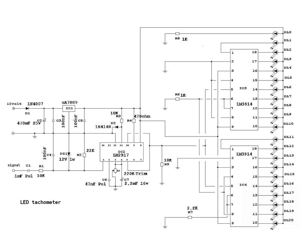
The described circuit is designed to drive a series of LEDs in either a bar graph or dot mode configuration, allowing for versatility in visual representation of RPM readings. The circuit utilizes an integrated circuit (IC) to control the LED outputs based on the input signal derived from the ignition coil. Each unit can manage up to 10 LEDs, with an additional LED included for status indication, resulting in a total of 21 LEDs that can be configured in various colors to enhance visibility.
The switching mechanism between bar mode and dot mode allows users to select their preferred display format, providing flexibility based on user requirements or preferences. The necessity for bright LEDs is emphasized, particularly when using covers that may obscure light output. The choice of LED colors can be tailored to suit aesthetic preferences or functional requirements, such as using red LEDs to indicate a critical RPM range.
The input signal from the ignition coil is a crucial element of the circuit's functionality. It is typically a square wave signal that correlates with the engine's RPM; as the engine speed increases, the frequency of this signal rises. The circuit must be calibrated to accurately interpret this signal, ensuring that the LED outputs reflect the correct RPM. Any discrepancies in the signal, such as incorrect voltage levels or signal type (positive vs. negative), can lead to malfunction, necessitating careful attention to the ignition system's characteristics.
In instances where access to the negative terminal of the ignition coil is challenging, an inductive pickup method can be employed. This involves wrapping a wire around the spark plug wire to capture the electromagnetic field generated during ignition, thus providing an alternative means of obtaining the RPM signal without direct electrical contact.
The implementation of a trimpot allows for fine-tuning of the circuit, enabling adjustments to be made for optimal performance. However, the use of incorrect component values, such as the trimpot or capacitor types, can hinder the circuit's operation. It is essential to adhere to the specifications outlined in the datasheet for the IC to ensure proper functionality.
Overall, the circuit presents a practical solution for RPM monitoring in automotive applications, particularly for projects such as FSAE vehicles. Proper assembly, calibration, and testing are critical to achieving reliable performance, and users are encouraged to troubleshoot common issues related to component selection and signal integrity to ensure successful implementation.Each one can drive 10LEDs in either bar mode like this project or dot mode. Switching between both modes can be done, more instructions in datasheet. 21 LEDs of any color you want. I used bright white ones. You can use some green, some yellow & some red for the red zone. You MUST use bright ones if you are planning to put paper covers over the LEDs or they are going to be simply invisible Not really sure. You can download the PDF datasheets of both & compare to see weather it`s possible to replace LM2917 with LM2907 & what changes should be made to the circuit hi sir, I am working for FSAE. I need RPM meter for my FSAE car. Can you tell me what kind of input from that Ignition coil Is that circuit is correct make it sure. I tried many times. But it was not working. can u mail me exact circuit. Do you Seriusly works for FSAE The circuit works, not as perfect as it is showed in the video in my case, but it works.
I dont know how the input signal is, but i guess that it is a square signal that increases in frecuency as the RPM increase. This circuit works BUT need some adjust. I will take a look over the circuit and see how to impruve it because now it is almost working in my case.
My issues could be caused by voltage provided for the coil and the power supply provided for the tachometer. I am finaly done with this projekt but on my first test led 0 is on and all looks good but, when i start the car led 1 goes on and only change in brightnes when i change the RPM.
Any idG©e whats wrong I have 2 meter cable betwen the circuts and the Led s, might that be the problem Will appreciate any answer. Now after some time. i started to look at this project again and i see that i have a 2, 2Kohm Trimpot not 220Kohm. Ordered one and will se if this fix the problem. i am having this same problem, i know its been a while but what car were you trying it with i have an 86 300zx and a 2000 civic that both do the same thing.
I made this circuit and it doesnt seem to be working. i plug it into the tach wire and it goes to one spot then stays there like the frequency is staying the same. it also looks like i used polyester caps instead of polypropylene, could this be why I dont even know if somebody is following this instructable anymore.
I have a honda cbr 600 and my tach broke. I googled and found your blog. I am not educated in electronics but know how to follow instructions. When I wanted to test it in real life I just realised that the ignition coils are mounted inline for each spark plug in my cbr and it is like impossible to get to the -ve terminal. I wanted to ask, can we modify this circuit in any ways so that it can pick up the signal using induction i.
e. by wounding a cable around the spark plug wire externally and not the actual signal from the ignition. I just completed Led drive part of this circuit, but I have a problem: I use 20 cm leads to connect from IC 3914 to LED, all LED are lit when no input.
The data sheet of 3914 instruct to connect 2 microF from +Led lead to pin 2(-) of IC but it can not fix the problem. Pls help me. doducthaivg@yahoo. com Dear aoa, you have done a great job. Thumb Up. Dear you have mentioned in tachometer gauge that signal should be from the negative of coil that means its negative signal in your.
But sir mine engine produce positive signal for RPM so how should i solve this problem. Please also provide me your email. hey so ive never really purchased components like what you have here for your parts list, where is the best place to buy these thank you very much, and for a total cost of the project you said it was about 6 dollars USD If you guys are not able to get it to work, double check your connections! Also beware of the ignition coil polarity, I had to keep switching back and forth because the polarity wasn`t marked clearly enough to see until I had to get very close to the coil.
salam, hosni. i wa 🔗 External reference
Related Circuits
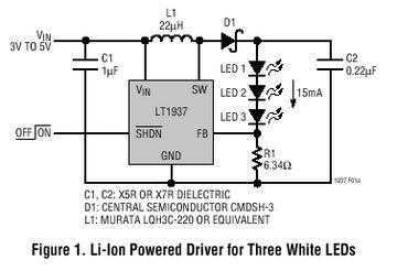
The LT1937 is a step-up DC/DC converter specifically designed to drive white LEDs with a constant current. The device can drive two, three or four LEDs in series from a Li-Ion cell. Series connection of the LEDs provides identical...
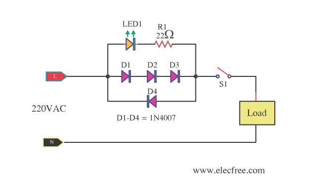
A need exists for a 220V AC line light display or main voltage monitor due to frequent electrical issues in a home. To create a 220V AC line light display or voltage monitor, a circuit can be designed using a...
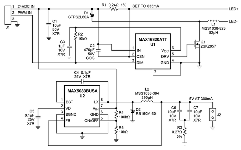
A reference design for a 4S1P MR-16 LED driver that provides 750mA to a string of four white LEDs (WLEDs). The circuit operates from a 24V source and is based around the MAX16820 hysteretic LED driver. Also included is...
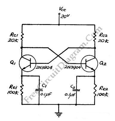
This flip-flop circuit functions as a free-running astable multivibrator, where the bases and collectors of both emitter-biased transistors are directly coupled. The switching action is facilitated by a capacitor in each emitter circuit, resulting in the generation of triangle...
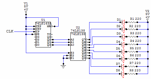
This is a very simple circuit to build, just take note of the control pins on each IC, since both have enable inputs for counting or output, but once set you don't need to worry about them. From left...
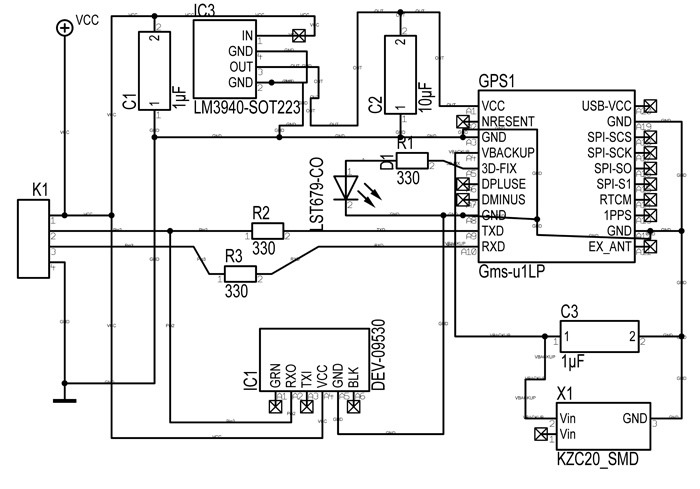
Following last year's rediscovery of radio-controlled flight, there is a growing interest in the hacking and modification potential of the budget-friendly 9-channel FlySky FS-TH9X transmitter (also marketed as Turnigy/Eurgle, etc.). The original 2.4GHz RF module and firmware are quite...
Warning: include(partials/cookie-banner.php): Failed to open stream: Permission denied in /var/www/html/nextgr/view-circuit.php on line 713
Warning: include(): Failed opening 'partials/cookie-banner.php' for inclusion (include_path='.:/usr/share/php') in /var/www/html/nextgr/view-circuit.php on line 713