
LED runner with 74LS163
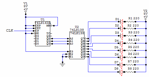
The circuit described utilizes a 74LS163 binary counter and a 74LS138 demultiplexer to create a visually appealing LED chaser effect. The 74LS163 is a 4-bit synchronous binary counter that counts up in binary with each clock pulse applied to its clock input. Its enable inputs allow for control over the counting operation, which means that once the circuit is configured, these pins can be set to a stable state to allow continuous counting without further intervention.
The output of the 74LS163 provides binary values that correspond to the current count, which are fed into the 74LS138 demultiplexer. The 74LS138 takes these binary values and activates one of its eight outputs (Y0 to Y7) based on the input address. Each output pin can be connected to an LED, which will illuminate in sequence as the counter increases, creating the moving light effect.
For proper operation, an external clock signal is required to drive the counting process of the 74LS163. This clock can be generated using a simple oscillator circuit or a push-button switch for manual control. The design allows for easy expansion; by utilizing the Q3 output of the counter, it is possible to enable a second 74LS138 demultiplexer, effectively allowing the circuit to control up to 16 LEDs. This can be achieved by connecting the Q3 output to the enable pin of the second demultiplexer, thus doubling the number of sequentially lit LEDs.
Overall, the simplicity and flexibility of this circuit make it an excellent choice for beginners in digital electronics, while also providing opportunities for more advanced modifications and expansions.This is a very simple circuit to build, just take note of the control pins on each IC, since both have enable inputs for counting or output, but once set you don't need to worry about them. From left to right, the first IC is a binary counter, 74ls163, that is used to generate the address numbers we are going to use in the second part of the circuit, the demultiplexer 74ls138.
This Led chaser is built using some very common digital logic circuits. Easy to build, easy to work with, and looks amazing in the dark. This circuit will light each led in sequence, creating a moving light illusion. This demux is the core of the circuit, as this IC pulls low the pin selected in the address inputs. Note that you need an external clock for the counter to work (count). It can also be extended to 16 leds by using the Q3 output of the counter to control the enable inputs of a second demultiplexer, or just add a second one to generate a double pattern. 🔗 External reference
Related Circuits
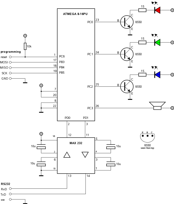
Building a computer-controlled LED lamp with an ATMEL microcontroller. The project involves designing a computer-controlled LED lamp utilizing an ATMEL microcontroller as the central processing unit. The core components of this circuit include the ATMEL microcontroller, a power supply, various...
A voltage-controlled oscillator is an oscillator whose frequency of oscillation can be varied by changing an applied voltage. A voltage-controlled oscillator (VCO) is an essential component in various electronic systems, particularly in communication devices, signal processing, and modulation applications. The...
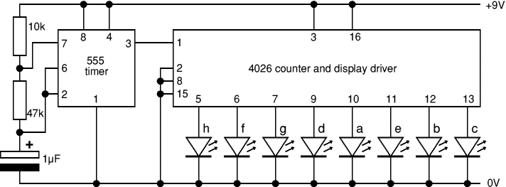
This project flashes eight LEDs in a seemingly random manner. It utilizes a 4026 combined counter and display driver integrated circuit (IC) designed for driving 7-segment LED displays. The sequence is not entirely random, as seven of the LEDs...
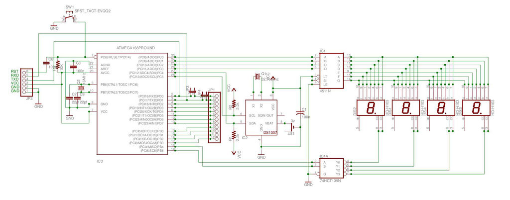
This is the second instructable focused on creating a digital watch as a learning experience. An Atmega644 chip from a Sanguino was available, which would have sufficed, but the intention was to burn an Arduino bootloader and test its...
Create LED lighting powered directly from the AC mains (120-Volt AC) due to the unavailability of inexpensive and safe enclosures for the circuitry. While collecting old failed CFLs for recycling, it was noted that the body of CFLs (also...
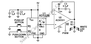
In various electronics-level adjustments, such as LED drivers for LCD panel backlight controls, the AD5228 can be utilized. A manually adjustable LED driver is illustrated. The AD5228 is a dual-channel, digitally controlled potentiometer (DCP) that can be employed in applications...
Warning: include(partials/cookie-banner.php): Failed to open stream: Permission denied in /var/www/html/nextgr/view-circuit.php on line 713
Warning: include(): Failed opening 'partials/cookie-banner.php' for inclusion (include_path='.:/usr/share/php') in /var/www/html/nextgr/view-circuit.php on line 713