
Direct Coupled Discrete Astable Multivibrator circuit
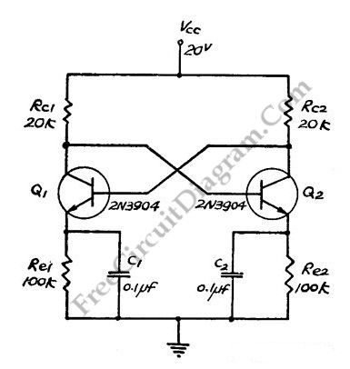
The described circuit operates as an astable multivibrator, utilizing two NPN transistors configured in a feedback loop. Each transistor's base is connected to the collector of the other, creating a regenerative feedback mechanism essential for continuous oscillation. The capacitors in the emitter circuits play a crucial role in determining the timing characteristics of the oscillation. Specifically, they charge and discharge, causing the transistors to switch states alternately.
In this configuration, the triangle wave output is generated due to the charging and discharging cycles of the capacitors, which control the timing of the transistor switching. The frequency of the oscillation can be adjusted by varying the capacitance of the capacitors or the resistances in the circuit. The use of a single 0.1 µF capacitor simplifies the design, reducing component count while maintaining the functionality of the circuit.
The output can be taken from the emitters of the transistors, where the triangle wave can be utilized in various applications, such as waveform generation, signal modulation, or as a clock signal in digital circuits. Proper biasing of the transistors is essential to ensure they operate in the active region, allowing for stable oscillation without distortion in the output waveform. The circuit's simplicity and effectiveness make it a popular choice for generating oscillating signals in electronic applications.This flip-flop circuit is a free running/astable multivibrator one, with bases and collector of both emitter biased transistor are directly coupled to each other. Switching action is supported by means of capacitor in each emitter circuit. This configuration produce a triangle waves at emitters. Since neither transistor can remain permanently cut off, then a free running oscillation will be generated. We can use single 0. 1 uF capacitor between emitters in place of C1 and C2. 🔗 External reference
Related Circuits
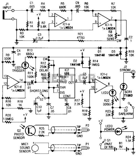
Sound or light sensors connected to J2 produce a voltage that is amplified by IC1-a and IC1-b. A positive trigger voltage developed by D1 and R3, and amplified by IC1-d, drives IC2 and IC1 to trigger SCR1. SCR1 is...
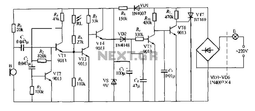
This circuit design is a sound and light control delay switch for staircase walkway lighting, featuring high voice sensitivity. In the evening, when someone walks on the stairs, their footsteps activate the electronic meter, turning on the lights. If...
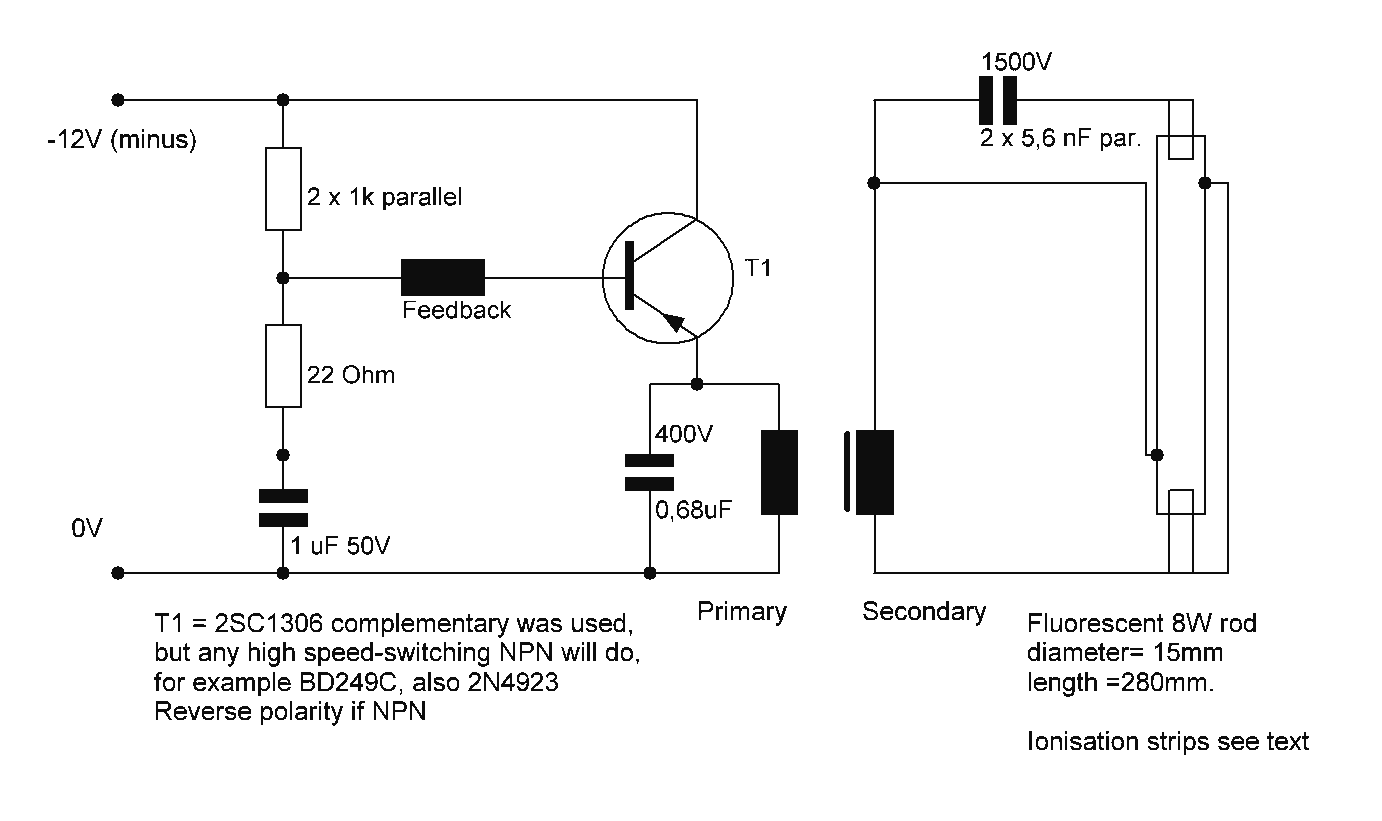
Starting a fluorescent lamp on an inverter can be challenging due to the trade-offs involved in achieving optimal operating efficiency with 12V drivers. Fluorescent lamps require a specific starting voltage to ionize the gas within the tube and initiate the...

A neon lamp can easily be added to the phone line to act as a ring indicator. It is perfect for times when you cannot hear the phone. The integration of a neon lamp as a ring indicator in a...
This is the large controller utilized for the game Steel Battalion for the Xbox. The schematic diagram was sourced from an individual named Alpha who created it for his own use. The Steel Battalion controller is a specialized input device...
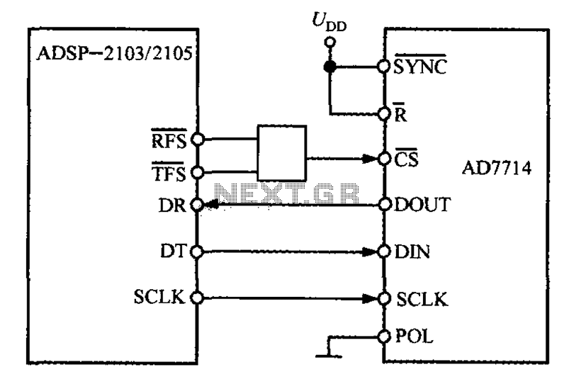
The ADSP-2103 and ADSP-2105 are digital signal processors that interface with the AD7714. When the output is active, the ADSP-2103/2105 configuration includes the RFS non-TES non-terminal set to a low level, while the SCLK terminal is configured for serial...