
DIY parking sensor
To design a cost-effective parking sensor, a basic understanding of ultrasonic sensor technology is essential. The parking sensor system typically consists of an ultrasonic sensor, a microcontroller, a power supply, and an output indicator, such as a buzzer or LED.
The ultrasonic sensor emits sound waves at a frequency beyond human hearing. When these sound waves encounter an object, they reflect back to the sensor. The time taken for the sound waves to return is measured, allowing the system to calculate the distance to the object. This data is then processed by the microcontroller, which interprets the distance and triggers the output indicator based on predefined thresholds.
The microcontroller can be programmed to activate the buzzer or LED at specific distances, providing audio or visual feedback to the driver. For instance, the buzzer may sound continuously when the vehicle is within one meter of an obstacle, while an LED may flash to indicate proximity.
Power can be supplied using a battery or a DC adapter, ensuring the system is portable or can be integrated into the vehicle's electrical system. The entire assembly can be mounted discreetly on the vehicle, allowing for unobtrusive operation while enhancing safety during parking maneuvers.
In summary, a parking sensor can be constructed with minimal components and at a low cost, making it an accessible project for electronics enthusiasts.Read the article and learn how you can make your own parking sensor for just $4.99. 🔗 External reference
Related Circuits

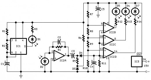
The 15 kHz frequency is used to drive the flyback transformer; however, the high voltage at the output is DC. The flyback transformer operates by converting low-voltage DC into high-voltage DC, utilizing a specific driving frequency, in this case, 15...
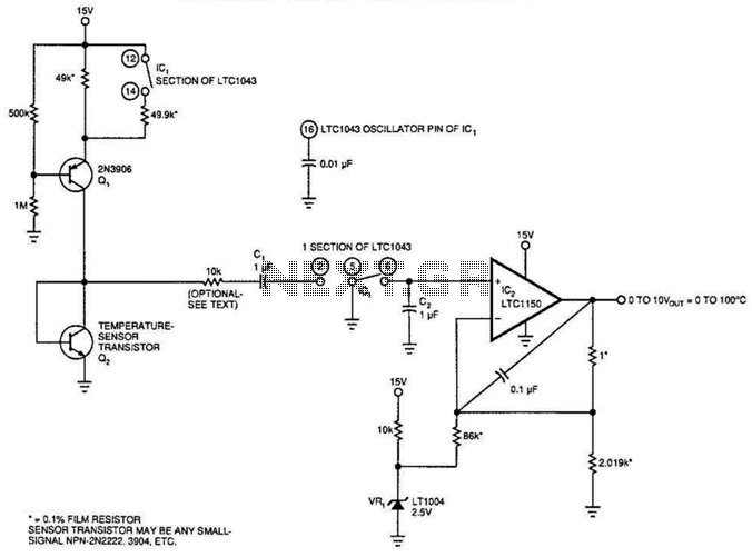
Using the fact that the VRE of a transistor shifts 59.16 mV per decade of current at 25°C. This constant is 0.33%/°C. This V5E-vs.-current relationship holds true regardless of the FBe absolute value. IC, an LT1043, acts as an...
A differential temperature sensor is employed to measure the temperature difference between two distinct areas. The schematic diagram of the circuit is provided for reference. The differential temperature sensor circuit typically consists of two temperature sensing elements, such as thermocouples...
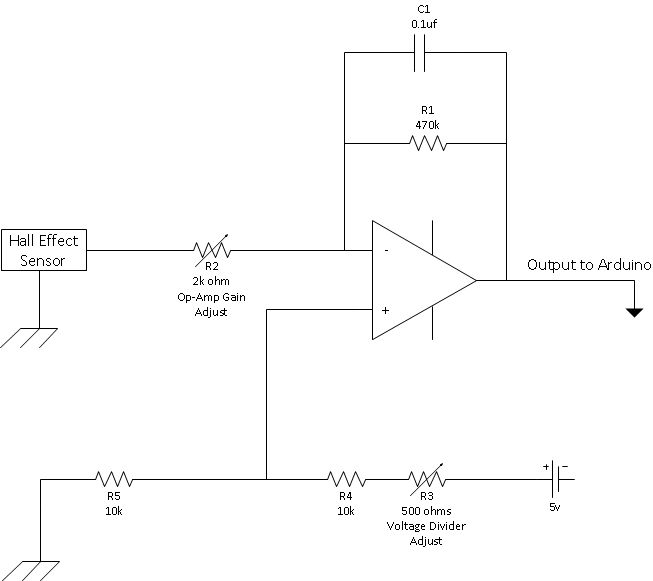
This is a straightforward schematic of an amplifier and filter. The circuit primarily features an LM124 operational amplifier configured in an inverting setup. The schematic illustrates a basic audio amplifier and filter circuit utilizing the LM124 operational amplifier. The LM124...
The oxygen sensor simulator is constructed on a protoboard. It utilizes a cigarette lighter plug as the power source. An adjustment knob is located on the left side, while a switch is positioned on the right. A red indicator...
A photo-activated normally open relay is employed in a circuit that interacts with light. In this configuration, a photodiode is utilized to detect light levels. The photodiode exhibits high resistance in the absence of light. It is connected in...