
Monitoring water usage with Hall effect sensor and Arduino

The schematic illustrates a basic audio amplifier and filter circuit utilizing the LM124 operational amplifier. The LM124 is a quad op-amp, which means it contains four independent, high-gain, frequency-compensated op-amps within a single package. This configuration allows for efficient use of space and resources in circuit design.
In the inverting configuration, the input signal is applied to the inverting terminal of the op-amp, while the non-inverting terminal is connected to ground. Feedback is provided from the output to the inverting input through a resistor, which sets the gain of the amplifier. The gain can be adjusted by changing the feedback resistor values. The output voltage is a negative amplified version of the input voltage, allowing for signal inversion.
Additionally, the filter aspect of the circuit can be achieved by integrating capacitors into the feedback loop or using them in conjunction with resistors to create low-pass or high-pass filters. The choice of capacitor values will determine the cutoff frequency of the filter, enabling the circuit to selectively amplify certain frequency ranges of the input signal while attenuating others.
Overall, this amplifier and filter schematic is ideal for applications requiring signal conditioning, such as audio processing or sensor signal amplification, where noise reduction and frequency filtering are essential for optimal performance.This is a fairly simple schematic of the amplifier and filter. At the core of the circuit is an LM124 op-amp running in an inverting configuration. Th.. 🔗 External reference
Related Circuits
A circuit is described that transmits temperature data over an IR link. This allows isolation of the temperature sensor. The circuit operates by utilizing an infrared (IR) transmitter and receiver pair to wirelessly transmit temperature readings from a sensor to...

The kit includes essential items to create your own Arduino 328 board, with components mounted on a breadboard running a demo LED flash program. The processor can be programmed directly from the Arduino IDE using a TTL serial connection....
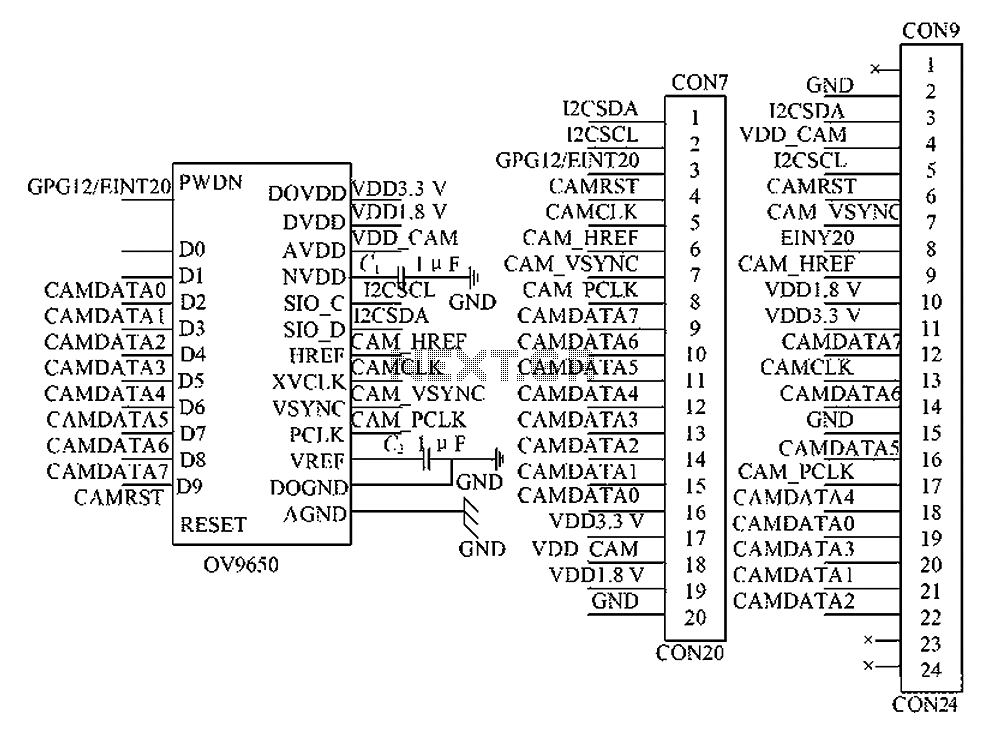
The circuit principle involves the OV9650 processor, which interfaces through three components: the SCCB interface, the data output interface, and the control interface. The SCCB interface is responsible for transferring initialization parameters from the processor's internal registers. It utilizes...
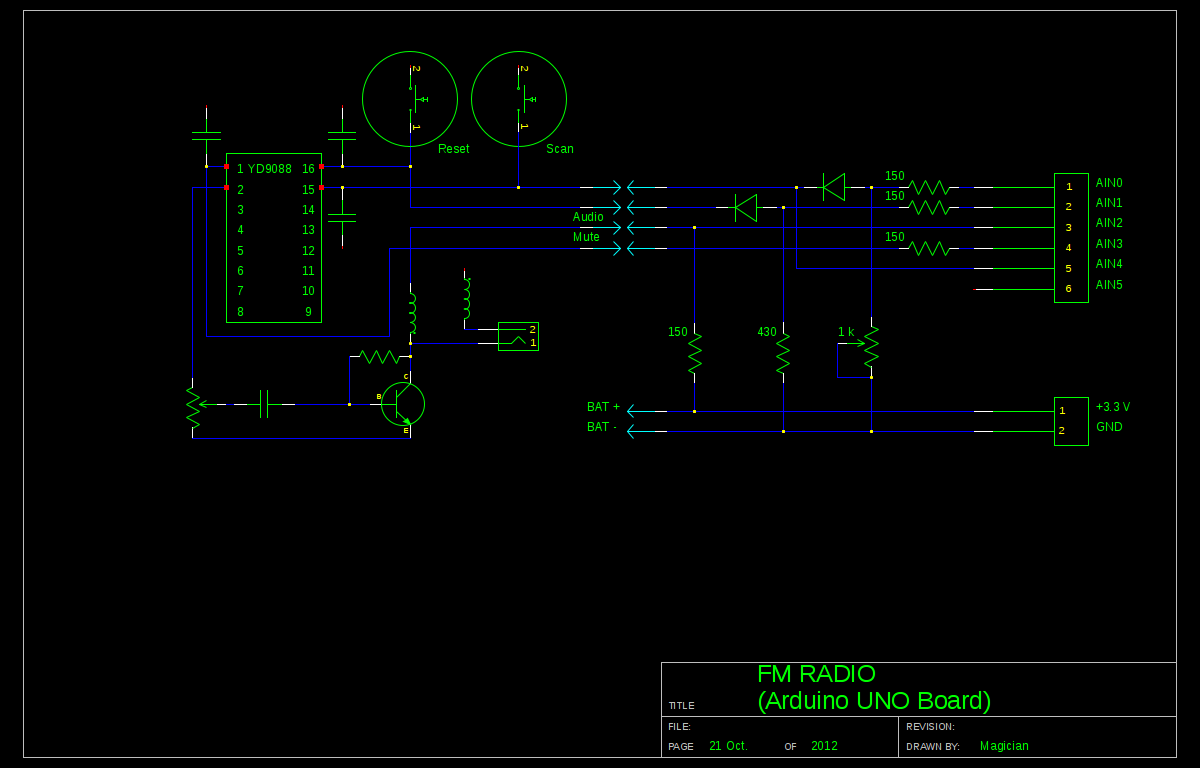
A local convenience store (Dollarama in Montreal, Canada) offers an appealing FM radio for just $3. The idea of interfacing this radio with an Arduino presents a fun challenge. Although the primary goal is not to create a radio,...
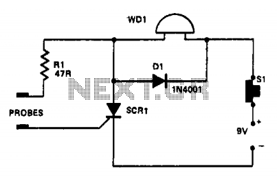
In this circuit, a warning device (WD1) is connected in series with a silicon-controlled rectifier (SCR1). When the liquid level creates a conductive path between the probes, the SCR becomes conductive, activating the warning device. The warning device can...
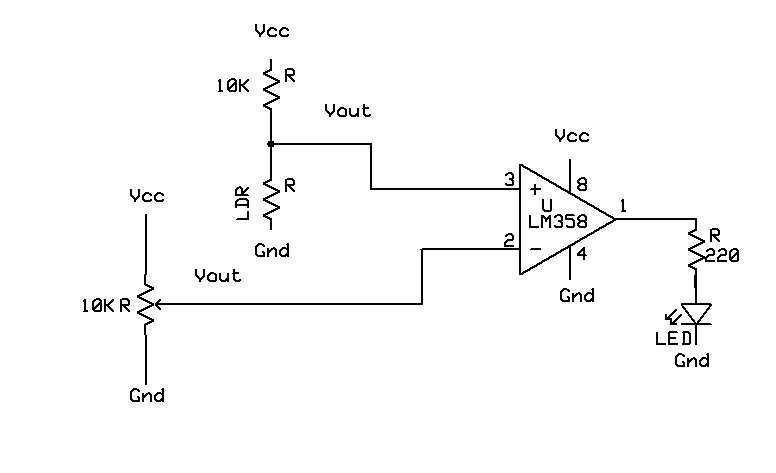
A light-based sensor utilizing an LDR (Light Dependent Resistor) and an operational amplifier (Op Amp). This circuit can be employed for applications such as line followers. The operation of the Op Amp is foundational to this design. It features...