
o2 sensor
The oxygen sensor simulator is a crucial tool for testing and diagnosing automotive engine management systems. It is designed to emulate the electrical characteristics of a real oxygen sensor, allowing for the evaluation of fuel mixture adjustments in response to varying conditions. The device operates by simulating a lean or rich air-fuel mixture, which is essential for tuning the engine's performance.
The protoboard setup facilitates easy modifications and adjustments, making it suitable for experimental purposes. The use of a cigarette lighter plug for power supply ensures compatibility with most vehicles, allowing for straightforward connection and operation. The adjustment knob provides a user-friendly interface to simulate different operating conditions. When the knob is rotated clockwise, it simulates a lean condition by reducing the output voltage, which in turn turns off the LED indicator. This behavior is representative of how an actual oxygen sensor would operate under similar conditions, prompting the engine control unit (ECU) to enrich the fuel mixture to maintain optimal combustion.
The inclusion of a digital voltmeter, although not shown in the images, is a vital feature that allows for real-time monitoring of the voltage output from the simulator. This feedback can be invaluable for diagnosing issues within the engine management system.
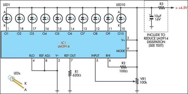
The choice of a red LED is significant; its forward voltage drop is accounted for in the circuit design, ensuring that the simulator operates correctly under varying conditions. Adjusting the capacitance of C1 can significantly impact the circuit's response time. A lower capacitance value, such as 4.7 µF, increases the oscillation frequency, allowing the simulator to more accurately replicate the rapid switching behavior of a new oxygen sensor. This adjustment can provide more precise simulation results, making the device more effective for testing purposes.
Overall, the oxygen sensor simulator serves as an essential diagnostic tool, providing valuable insights into the performance and behavior of automotive fuel management systems. Its design allows for flexibility and adaptability, making it suitable for both educational and practical applications in the field of automotive electronics.The oxygen sensor simulator as built on a protoboard. Note the cigarette lighter plug used for power source. The adjustment knob is at the left, and the switch is on the right. The red indicator LED is in the middle. Only use red, because the voltage drop of the LED is part of the circuit! The schematic diagram for the simulator. Closing the switc h engages the simulator. Turning the knob clockwise simulates a lean condition, turns the LED off, and the car should start running rich to compensate. The big "V" is a digital voltmeter(not shown in the pictures). Using a smaller value for C1, perhaps 4. 7 uF, will make the circuit oscillate faster and might be more like a real oxygen sensor(a new sensor switches more often than an old one).
🔗 External reference
Related Circuits

This light sensor circuit, utilizing a photosensor, serves as a bridge between light and electronics. It is constructed using an operational amplifier and the PIC16C63 microcontroller to control the sensor. While the circuit is not intended for precision applications,...
This project involves the design of an air-filter sensor intended for use in home heating and cooling systems. The project encompasses conceptual design, analysis, implementation, testing, and modifications. Initially, the study focuses on comparing air quality and power consumption...
The circuit operates but exhibits instability, particularly with temperature variations. For example, upon powering it on and tuning it, switching it off and on again affects its performance. The control voltage (CV) output is essential for the theremin/controller circuit....
Close to human perception and stable color sensing is a pervasive challenge encountered in various disciplines, such as machine vision for classification and recognition, as well as in intelligent systems like smart illumination systems in home or workplace environments....

This is a TMP01 Temperature Sensor Transmitter circuit. This circuit is used in industrial environments to transmit the signal differentially on a wire pair. The TMP01 Temperature Sensor Transmitter circuit is designed to provide accurate temperature measurements in industrial settings,...
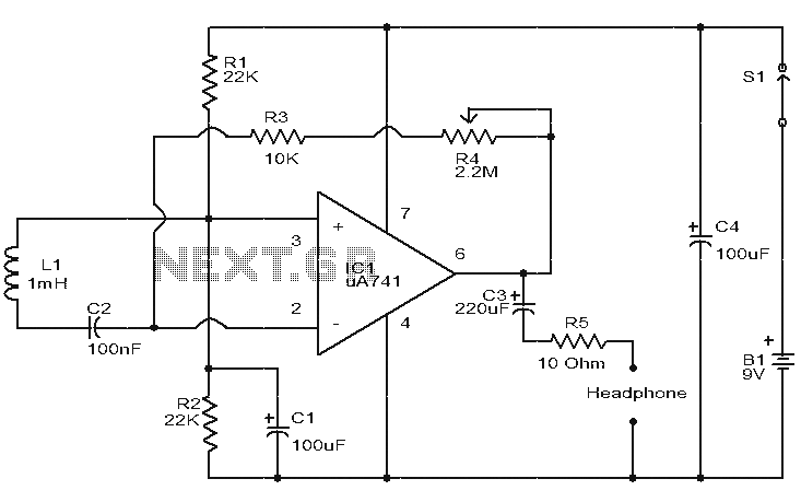
This is a simple circuit designed to detect electromagnetic radiation, including hidden wiring. It utilizes a 1mH inductor to sense the electric field. The induced voltage from the inductor is amplified by an operational amplifier (op-amp). An audio headset...