
diy solar cell phone usb charger
The circuit operates on a straightforward principle of converting solar energy into electrical energy to charge rechargeable batteries. The solar panel acts as the primary energy source, converting sunlight into electrical voltage. The diode serves as a protective component, preventing reverse current flow that could discharge the batteries back into the solar panel when sunlight is not available. The four Ni-MH rechargeable batteries are connected in series, providing a combined nominal voltage of 5 volts, which is suitable for USB charging applications.
The design should include a USB type "B" female port, allowing for easy connection to various devices. The batteries should be housed in a secure compartment to prevent movement and potential damage. Additionally, incorporating a voltage regulator may enhance the circuit's performance by ensuring a stable output voltage, regardless of variations in battery charge levels.
It is essential to ensure that the solar panel is positioned for optimal sunlight exposure to maximize charging efficiency. Regular maintenance of the solar panel and batteries will help maintain performance and longevity. Users should be advised to monitor the charging process and avoid overcharging, as this can lead to reduced battery life and efficiency. Proper usage and adherence to recommended charging times will ensure that the DIY solar cell phone or USB charger operates effectively and reliably.Here is the schematic of a simple DIY solar cell phone or USB charger circuit. This solar USB battery charger circuit can be used to charge any device, which can be charge from computer USB port. For example MP3 players, cell phone, iphone etc. The circuit is using a solar panel of 7 to 7. 2 volts, one diode and four Ni-MH rechargeable batteries of 1. 25 volt and 2000 mAh and a USB type "B" female port. The fully charge batteries will show 5 volt on the digital millimeter which is an ideal voltage to for a USB charger. panel of 7 to 7. 2 volts, one diode and four Ni-MH rechargeable batteries of 1. 25 volt and 2000 mAh and a USB type "B" female port. The fully charge batteries will show 5 volt on the digital millimeter which is an ideal voltage to for a USB charger.
After completing the circuit check the voltage of your new Ni-MH batteries with your digital multimeter, new batteries are often 50 or 70 percent charged by the manufacturers. if your batteries are not showing 5 or 5. 1 volt then charge them for 3 to 4 hours by placing the solar panel in direct sunlight. If you batteries are fully discharged then charge them 8 hours if your solar panel output current is 250mA in direct sunlight or 10 hours if your solar panel output current is 200mA in direct sunlight.
After charging the batteries in sunlight again check your batteries voltage with multimeter now if your batteries are showing 5 or 5. 1 volt then your DIY solar cell phone or USB charger is ready to charge your devices. Next time when your solar charger batteries require charging charge them only 3 to 4 hours cycle. Do not charge your devices at the same time when you are charging the batteries of your solar USB charger.
First charge your USB charger batteries and then remove it from the sunlight and then connect your devices to charge. Do not charge your batteries more than 8 to 10 hours. 🔗 External reference
Related Circuits
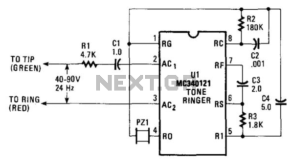
The AC ringing voltage, typically ranging from 40 to 90 V at 26 Hz, is rectified by U1, the tone-ringer integrated circuit (IC), which is utilized to drive the internal tone-generator circuitry. This tone-generator IC comprises a relaxation oscillator...

Illuminate your tabletop with this stylish White LED Lamp. It is powered through a USB port, making it perfect for taking notes while browsing the internet. The USB port can provide a convenient power source. The White LED Lamp is...
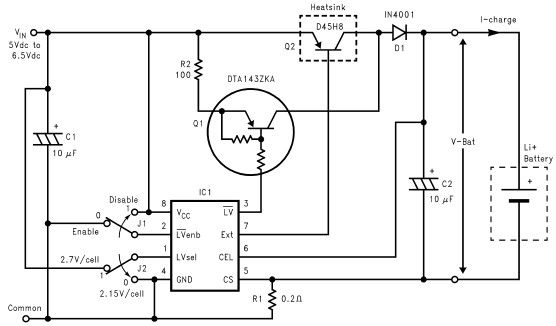
Lithium-ion charger circuit design electronic project using LM3632 controller. The lithium-ion charger circuit utilizing the LM3632 controller is designed to efficiently charge lithium-ion batteries while ensuring safety and longevity. The LM3632 is a highly integrated, step-down linear charger specifically tailored...
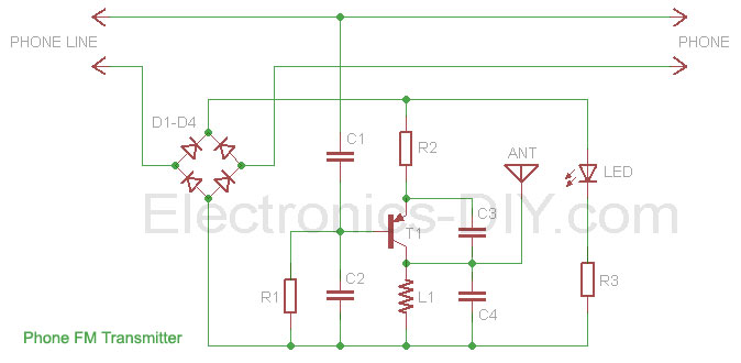
This phone FM transmitter connects in series to a telephone line and transmits telephone conversations over the FM band when the telephone handset is picked up. The transmitted signal can be tuned by any FM receiver. The circuit includes...
The heart of the Chloroplast is the Motorola MC34164-3 Micro power Undervoltage Sensing Circuit (U1 in the following diagram). In normal use, this component monitors the voltage at pin 2, and applies a ground at pin 1 (out) when...
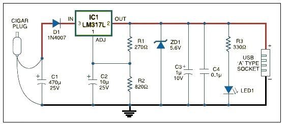
USB car charger adapter circuit design using LM317 regulator circuit The USB car charger adapter circuit utilizing the LM317 voltage regulator is designed to convert a car's 12V DC power supply into a stable 5V output, suitable for charging USB-powered...