
Lithium Ion charger circuit using LM3632
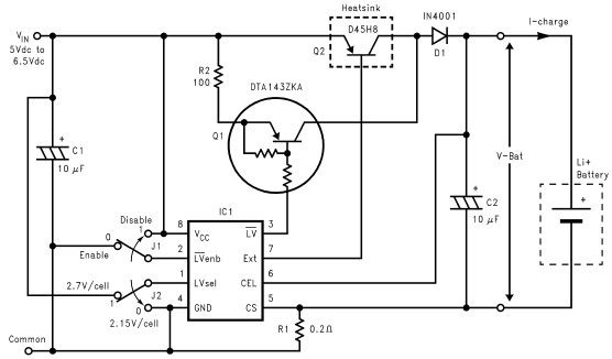
The lithium-ion charger circuit utilizing the LM3632 controller is designed to efficiently charge lithium-ion batteries while ensuring safety and longevity. The LM3632 is a highly integrated, step-down linear charger specifically tailored for lithium-ion batteries, offering features such as constant current and constant voltage regulation.
The circuit typically includes the LM3632 IC, which manages the charging process by providing a constant current to the battery until it reaches a preset voltage level. Upon reaching this voltage, the controller switches to constant voltage mode, maintaining the battery voltage while gradually reducing the charging current to prevent overcharging.
Key components of the circuit include input and output capacitors that stabilize voltage levels, a sense resistor that monitors the charging current, and a feedback network that ensures the output voltage remains within the specified range. Additionally, protection features such as thermal shutdown and overcurrent protection are integrated to enhance safety during operation.
The charger circuit may also incorporate LED indicators to signal the charging status, providing visual feedback to the user. The design should take into account the thermal management of the LM3632, as it may require a heatsink depending on the charging current and ambient conditions.
Overall, the LM3632-based lithium-ion charger circuit is an effective solution for charging lithium-ion batteries, balancing efficiency, safety, and user-friendliness in electronic projects.Lithium Ion charger circuit design electronic project using LM3632 controller. 🔗 External reference
Related Circuits
This light sensor switch circuit enables the automatic activation of a lamp when ambient light levels are low, such as during nighttime. The circuit keeps the lamp illuminated for a predetermined duration. When transistors T4 and T5 are activated,...
The subwoofer is a speaker designed to reproduce low frequencies, specifically in the range of 20 Hz to 150 Hz. The electronic circuit diagram below illustrates the details of a subwoofer amplifier using the TDA1516, a 22-watt amplifier suitable...
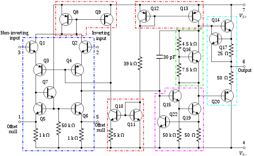
An operational amplifier, commonly referred to as an op-amp, is a DC-coupled high-gain electronic voltage amplifier featuring a differential input and typically a single-ended output. An op-amp generates an output voltage that is often millions of times larger than...
This is a very simple circuit utilizing a 555 timer IC to generate a square wave of frequency that can be adjusted by a potentiometer. With values given, the frequency can be adjusted from a few Hz to several...
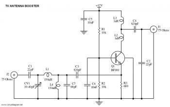
This is a straightforward circuit for a UHF band TV antenna booster that provides a gain of 15 dB. This low-cost antenna booster is simple and easy to construct. The UHF band TV antenna booster circuit is designed to enhance...
The FM302E-I-type FM transmitter exciter is manufactured by NEC Corporation, Japan, and features a 1210 motherboard. It utilizes direct frequency modulation of the carrier signal, employing phase-locked frequency stabilization and frequency synthesis techniques. The front power amplifier is based...