
DIY TDA2050 Hi-Fi Chip Amplifier (chipamp)
")
The TDA2050 is a popular audio power amplifier integrated circuit designed for various audio applications. This non-inverting amplifier configuration is particularly valued for its simplicity and effectiveness in delivering high-quality sound amplification. The project utilizes a protoboard for easy assembly and testing, allowing for modifications and adjustments as needed.
The circuit typically consists of the TDA2050 IC, which can deliver up to 14W of output power into an 8-ohm load with a total harmonic distortion of less than 0.1%. The essential components include the power supply, capacitors, resistors, and connectors for input and output signals.
To construct the circuit, the following steps should be followed:
1. **Power Supply**: The TDA2050 requires a dual power supply, typically ±14V to ±20V. Ensure that the power supply is regulated to prevent voltage spikes that could damage the IC.
2. **Input Stage**: Connect the input signal to the non-inverting pin of the TDA2050. A capacitor (typically 1µF) should be used to block any DC offset from the input source.
3. **Feedback Network**: A resistor divider network is used for setting the gain of the amplifier. The gain can be calculated using the formula: Gain = 1 + (R2/R1), where R1 is connected between the output and the inverting input, and R2 is connected from the inverting input to ground.
4. **Output Stage**: The output is taken from the speaker output pin of the TDA2050. It is essential to include a capacitor (typically 220µF) in series with the speaker to block DC and allow only the amplified AC signal to pass through.
5. **Decoupling Capacitors**: Place decoupling capacitors (typically 100nF) close to the power supply pins of the TDA2050 to filter out high-frequency noise and stabilize the voltage supply.
6. **Thermal Management**: The TDA2050 can generate heat during operation, so it is advisable to use a heat sink to dissipate heat effectively and ensure reliable operation.
7. **Testing**: After assembling the circuit, it is crucial to test the amplifier with a suitable audio source and load. Monitor the output for distortion and ensure that the amplifier operates within the specified parameters.
This DIY project provides an excellent opportunity to learn about audio amplification and circuit design while yielding a functional audio amplifier suitable for various applications, such as driving speakers in home audio systems or for experimental setups.DIY TDA2050 Non-Inverting Chip Amplifier (chipamp) Project constructed on a protoboard 🔗 External reference
Related Circuits
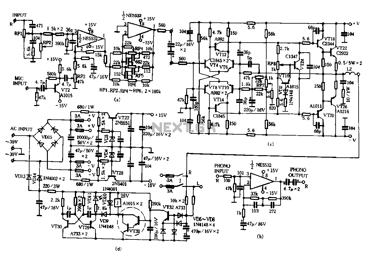
Only the R channel is shown, with the original reference PCB label. Figure (a) illustrates the front tone circuit, which consists of a common negative feedback operational amplifier in an RC circuit configuration. The microphone signal is amplified by...
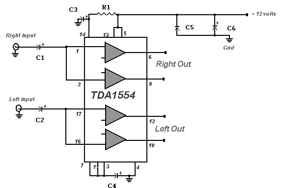
A 22 Watt stereo amplifier circuit diagram is presented. This circuit can be utilized for audio home amplifiers as well as car audio amplifiers. It features a straightforward design, is cost-effective, and is very easy to assemble, making it...
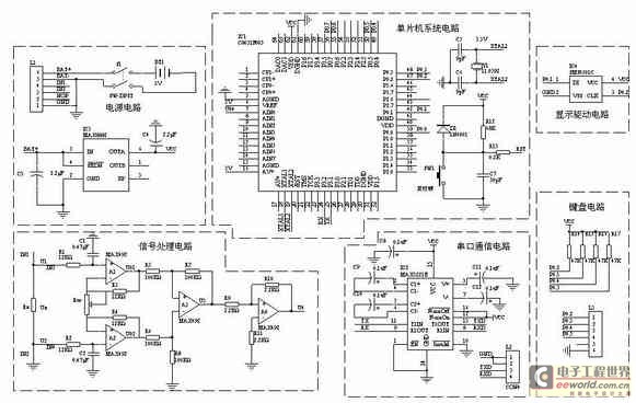
A one-chip computer has been utilized to design this survey meter, which directly displays the measured resistance on an LCD screen. The measurement range extends from 0 to 9999 kΩ, and the device can simultaneously store the measured data,...
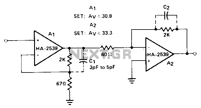
Cascaded amplifier sections are utilized to extend bandwidth and increase gain. By employing two HA-2539 devices, this circuit achieves a gain of 60 dB at 20 MHz. The design of the cascaded amplifier circuit involves connecting multiple amplifier stages in...
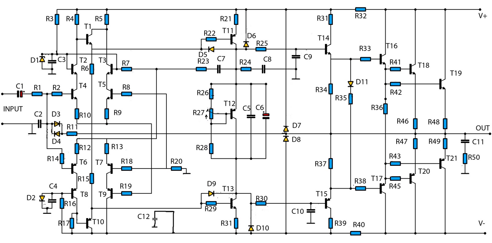
The mono high power amplifier is rated at 1400 W. To create a stereo high power amplifier, which would require a total of 2800 W, the necessary components and PCB must be doubled. The schematic circuit diagram provided is...
This is a circuit that ensures that you can connect two amplifiers together so you get more power. When called in bridge linking two amplifiers plus you can link the outputs of the amplifiers to the speaker. One of...