
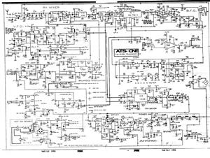
DK04 Monitoring Module and Computer communication interface circuit
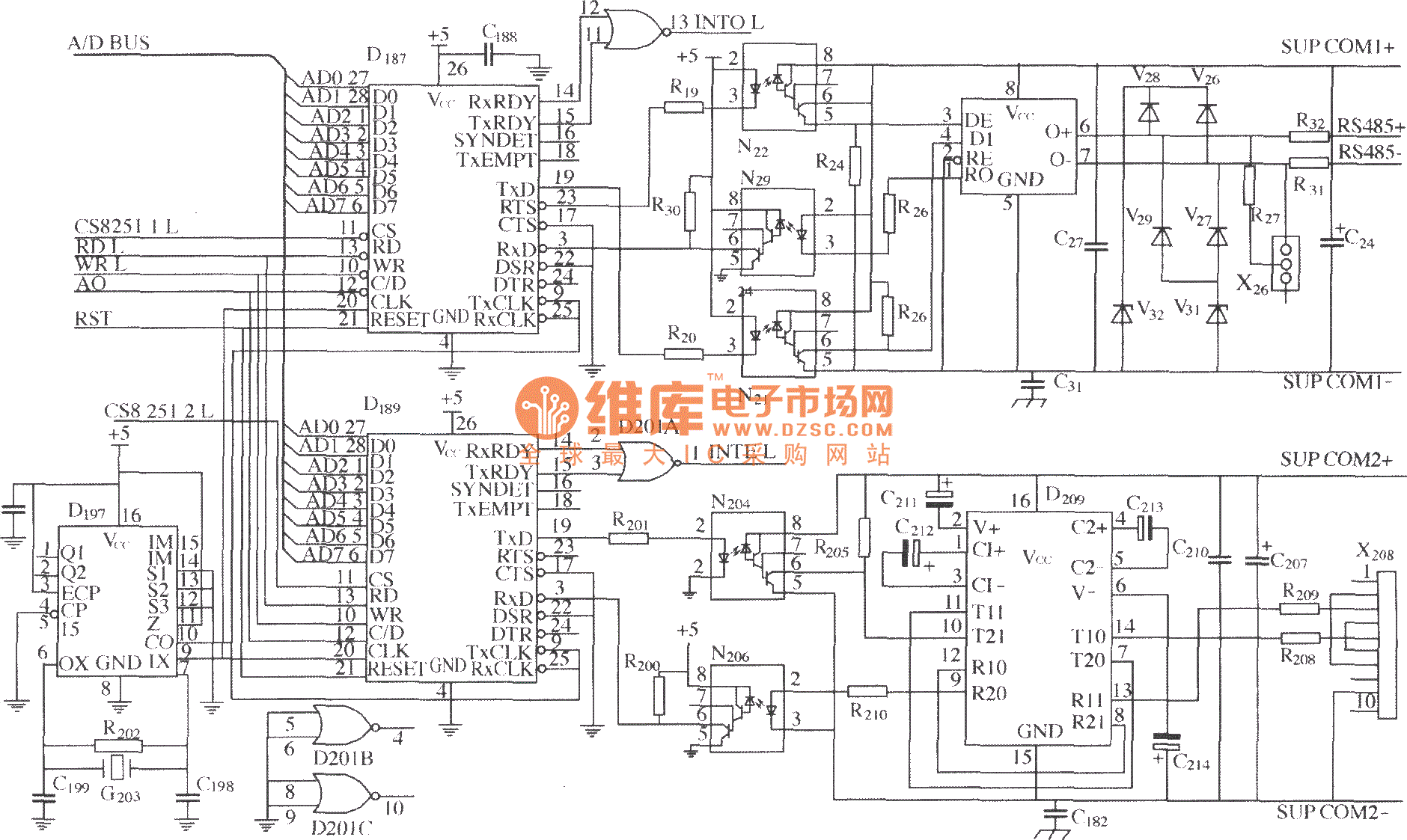
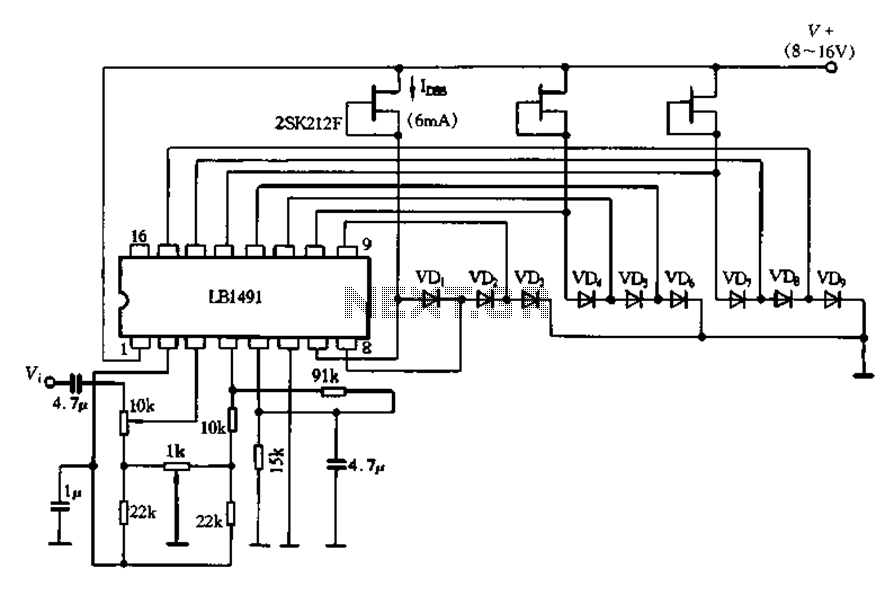
The described circuit utilizes several key components to ensure reliable communication in an isolated environment. The UART (Universal Asynchronous Receiver-Transmitter) D187 is responsible for serial communication, enabling data exchange between the microprocessor D211 and the RS-485 interface. The RX and TX signals from D187 are routed through optocouplers N21, N22, and N29, which serve to electrically isolate the microprocessor from the RS-485 communication line. This isolation is crucial for protecting sensitive components from voltage spikes and ground loops that may occur in industrial environments.
The RS-485 communication interface, represented by D28, is designed for long-distance data transmission and can support multiple devices on the same bus. This interface is particularly useful in applications requiring robust communication over significant distances, such as in industrial automation and control systems. The microprocessor D211 processes the data received from the RS-485 interface and can send commands back through the same channel.
D197 functions as a clock or timing generator, establishing a communication rate of 9600 bits per second. This baud rate is a standard choice for many serial communication applications, balancing speed and reliability.
Additionally, D189 represents another UART, which may be utilized for additional communication channels or redundancy in the system. This configuration allows for flexible data handling and can enhance the system's overall performance by enabling simultaneous communication paths.
This circuit exemplifies a well-designed approach to achieving optoelectronic isolation while maintaining effective data communication, ensuring that the microprocessor operates safely and efficiently in conjunction with RS-485 devices.As shown in figure, D187 is an UART, it`sRX / TX signalconnectedonoptocoupler N21, N22 and N29, so that put the RS-485communication interface receiver / transmitter D28and microprocessor D211 completely optoelectronicisolated. D197 is a generator, the currently communication rate is 9600bit / s. D189 is another universal asynchronous receiver transmitter. Op.. 🔗 External reference
Related Circuits
The multi-channel temperature measurement circuit is illustrated in the figure. The core of the test circuit comprises a 555 one-shot delay circuit. When the button is pressed, the output pin of the 555 timer (IC1) goes high due to...
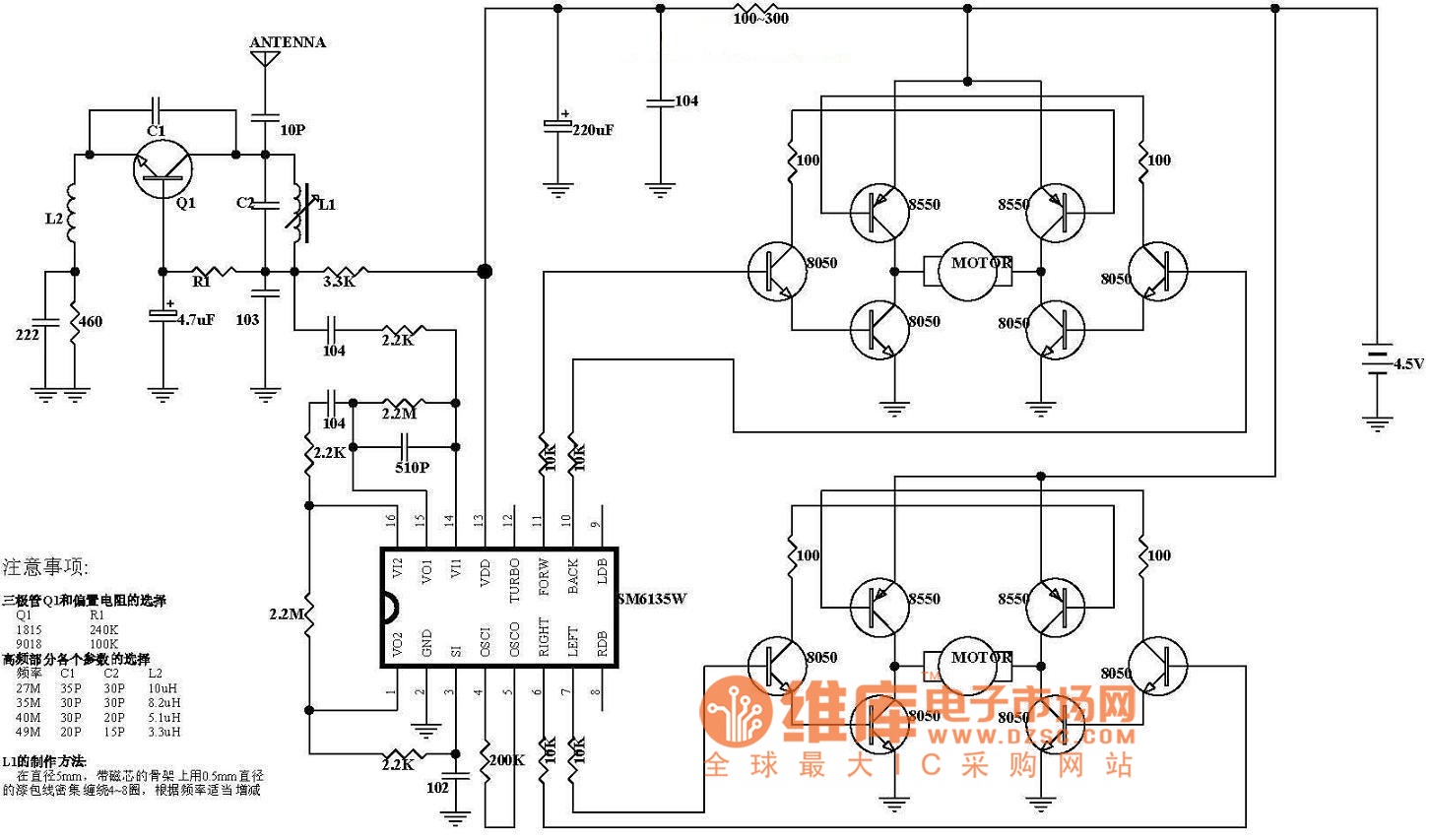
The diagram illustrates the principle circuit of a radio control car receiver. Important notes include the selection of transistor Q1, which is specified as either 1815 or 9018, along with the bias resistor R1, which has values of 240K...
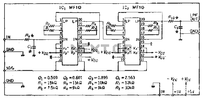
To create a Butterworth low-pass filter with a 12 dB/octave roll-off, four second-order (12 dB/oct) filter blocks are connected in series. This configuration is intended to achieve flat response characteristics across the frequency spectrum. The values for each stage...
This example describes the use of HS101 and HS201 radio transmitter and receiver modules to control rotating color lights, functioning as a multi-channel radio remote control device suitable for small dance floors or home use. Users positioned at any...
A display tube utilizing a constant current circuit to ensure a steady flow through the tube. The display tube operates on the principle of maintaining a constant current to achieve consistent brightness and performance. The circuit typically comprises a current...
The TS-440S, similar to several other radios, does not mute the microphone when utilizing the rear audio connector for digital modes. Consequently, unless the microphone is unplugged each time digital modes are used, background noise from the shack can...
Warning: include(partials/cookie-banner.php): Failed to open stream: Permission denied in /var/www/html/nextgr/view-circuit.php on line 713
Warning: include(): Failed opening 'partials/cookie-banner.php' for inclusion (include_path='.:/usr/share/php') in /var/www/html/nextgr/view-circuit.php on line 713