
radio circuit diagram
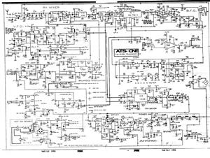
The schematic for this radio-controlled lighting system incorporates several key components to ensure reliable operation. At the transmitter side, the IC1 and IC2 work together to encode the control signals. IC1 generates the necessary control signals based on user input from the buttons, while IC2 modulates these signals for transmission. The use of a simple external resistor R2 helps maintain the stability of the oscillator circuit, ensuring consistent signal generation.
On the receiver side, IC3 receives the modulated signals transmitted by IC2. The internal amplifier within IC3 boosts the signal strength, allowing it to be effectively processed. The decoding function is handled by IC4, which verifies the user code and triggers the appropriate output based on the button pressed. The thyristor switches (VT4, VTH1, VTH2, VTH3) are crucial for controlling the power delivered to the lights and the motor, enabling smooth operation and brightness control. The design ensures that only one light can be controlled at a time when managing color brightness, preventing any potential conflicts in operation.
The power supply section, featuring a step-down transformer, ensures that the receiver circuit operates safely and efficiently at lower voltages. The bridge rectifier converts AC voltage to DC, while the capacitor filters any ripples, providing a stable voltage supply to the circuit. Overall, this schematic design offers a versatile and user-friendly solution for remotely controlling color lights, making it ideal for various applications in entertainment and home environments.This example describes use of HS101, HS201 radio transmitter and receiver modules made of radio-controlled rotating color lights, it is essentially a multi-channel radio remote control device codes for a small dance floor or home use. Users stand on any corner of the hall can be easily controlled with a remote control light color and brightness.
T he transmitter circuit diagram is shown in Figure a, which consists of coded radio transmitter module integrated circuits IC1 and IC2 constitute the core of the device; radio receiver decoder controller is shown in Figure b shows, mainly by the radio receiver module circuit IC3, decoding integrated circuit IC4, thyristor switch and power supply and other parts circuit. Relatively simple transmitter circuit, in addition to integrated circuits and application-specific modules, the external components small.
It has five control buttons SBl a SB5, SB1 is to control the rotation of the key light, press about, rotating lamps, and then press about, the rotation stops; SB2 SB4 is to control the color of a light but ton, the button is pressed, respectively, , can control the lights of a color in the most light, medium light and darkest; SB5 is a lights-out button, press this button, the lights go out. The principle is to change the color of red, green, and blue shade brighter than to achieve, but also can be rotated to change the light color palette.
IC1 15 yards for a 18 foot control for the user side, the high and low level (ie, ground pin, which of) the receiver must decode the data controller is exactly the same when the user code can only remote control, the aim is to achieve at the same venue How different is only the transmitter control both the receiver, because of user code data of different interference will not occur. R2 is the external oscillator resistor IC1. 11 feet from the output of IC1 anyone to the radio transmitter module coded pulse the input side IC2 IN, modulation of IC2, IC2 through the built-in antenna for the 280MHz frequency firing in the air around the radio waves.
SA for the transmitter power switch, close the SA, the transmitter power can only normal, VL is the transmitter working lights. Decoded at the receiving device in the pressing system. IC2 IC3 supporting the HS201 with radio receiver module that receives radio signals from the IC2, amplified by the internal circuitry of the module, modem, plastic, restore the original encoder pulse, the pulse decoder integrated circuit IC4 anyone to 6 feet, by the internal circuitry of the encoder pulse to compare identification, if the digital and IC4 pin 9 of a 12 user code data are identical, so that the output of the corresponding opening.
For example, pressing the transmitter SB1, receiving circuit IC4 output of 3 feet high, this high SCR VT4 by R3 to open, the motor M energized rotation. Block for the independent operation of this gear, that regardless of lamp is lit, can operate independently.
When you press the SB2 time, IC4 pin 1 output trigger pulses to VTH1 conduction through B5, as this pin turns the output pulse angle of the largest, ELI maximum brightness; When you press the SB3 when, IC4 of 18 feet, the output trigger pulse, the R6 to turn thyristor VTH2 medium, EL2 medium-brightness light hair; when pressed SB4 time, IC4 output trigger pulse of 17 feet, so VTH3 opened by R7, the output pulse because of the foot conduction angle minimum, so the EU made low light. SB2 SB4 is the interaction of a non-independent, that is, any time can only control three lights in any one, not simultaneously control 3 lights.
When pressed SB5, IC4 of 1, 17 and 18 feet without the trigger pulse output, ELI had a E13 due to the AC zero and all off. Receiver power from the 220V AC step-down transformer T, a bridge rectifier VDl VD4 and filtered by capacitor C3 voltage supply.
IC1 remote code should use HT6310 specific integrated circuit, the circuit is made using CMOS 🔗 External reference
Related Circuits
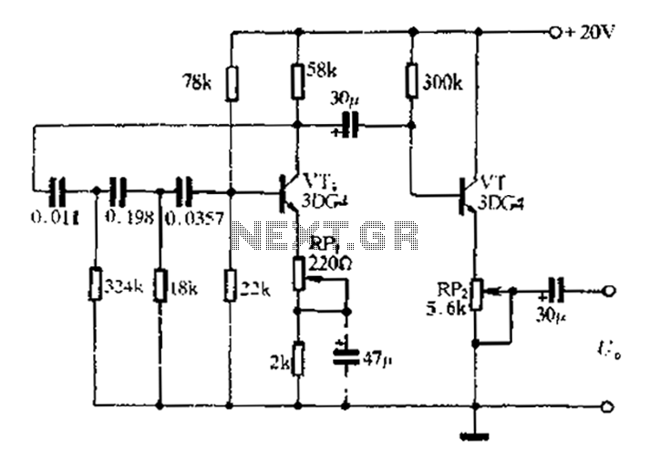
1 kHz RC phase shift oscillator circuit The 1 kHz RC phase shift oscillator circuit is designed to generate a continuous sine wave output at a frequency of 1 kHz. This circuit typically utilizes a combination of resistors and capacitors...
Police siren circuit diagram. This circuit produces a sound similar to a police siren. It utilizes two 555 timer ICs. The police siren circuit typically employs two 555 timer integrated circuits (ICs) configured in astable mode to generate a square...
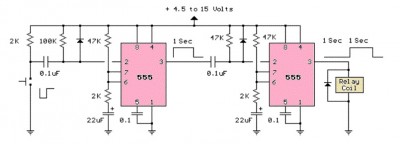
The LM555 timer circuit is similar to the previous design but incorporates two stages, allowing for control over both the pulse width and the delay. The LM555 timer is a versatile integrated circuit widely used in various timer, delay, pulse...
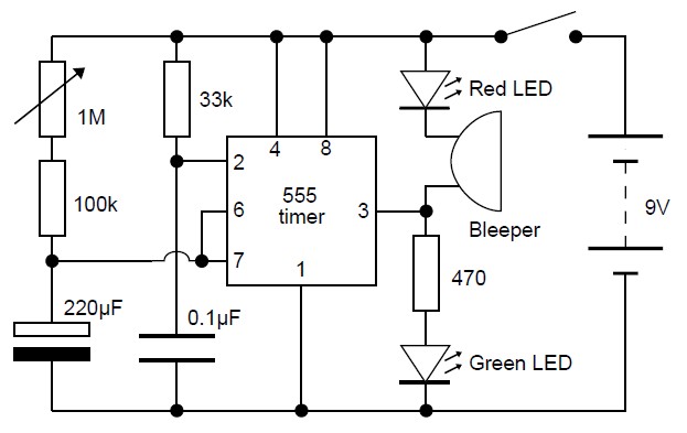
This adjustable analog timer circuit begins timing when it is activated. A green LED illuminates to indicate that the timing is in progress. Upon completion of the set time period, the green LED turns off, a red LED activates,...
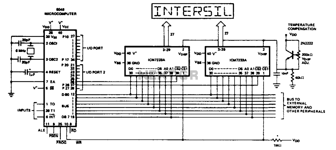
This is an 8048/IM80C48 microcomputer equipped with an 8-character, 16-segment ASCII triplex liquid crystal display. The two-bit character address is combined with the data and sent to the display driver under the control of the WR line. Port lines...
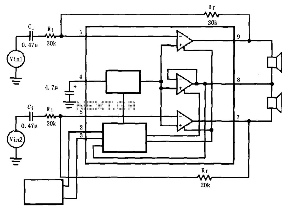
The LM4911 is presented in a configuration that does not utilize an output capacitor (OCL) for its power circuit. This design eliminates the need for squelch control (Mute), as the shutdown control (SD) responds more rapidly than the squelch...