
DMAl2 Main schematic circuit diagram

The DMA12 circuit is designed to enhance power efficiency and minimize electromagnetic interference, making it suitable for various applications requiring stable power supply and high performance. The input circuit is responsible for receiving the AC voltage, which is then processed by the EMI filter to suppress high-frequency noise that could affect the performance of downstream components. The impulse current limit circuit protects the system from sudden surges in current, ensuring reliable operation.
The input rectifier filter circuit converts the AC input into a DC voltage, which is essential for the subsequent boost/power factor correction circuit. This circuit steps up the voltage while improving the power factor, allowing for better utilization of the input power and reducing losses. The absorption circuit is designed to manage voltage spikes, providing a lossless method to absorb excess energy, thus enhancing the overall efficiency of the circuit.
The half-bridge power translation circuit is a key component that facilitates the DC/DC conversion process. It uses two switches to alternate the input voltage, effectively transforming it into a higher voltage output. The output rectifier filter circuit then smooths the DC output, ensuring a stable voltage is provided to the load.
Overall, the DMA12 circuit reflects advancements in power electronics, particularly in the areas of efficiency and noise reduction, while maintaining compatibility with its predecessor, DMA10. The design choices made in DMA12 contribute to its robustness and reliability in demanding electronic applications.The figure shows a simplified schematic diagram of main circuit DMA12. It is mainly composed of input circuit and electromagnetic interference (EMI) filter circuit, impulse current limit circuit, the input rectifier filter circuit, the boost / power factor correction circuit and the absorption circuit, half-bridge power translation circuit, the ou tput rectifier filter circuit. Compared with the DMA10, DMA12 uses single-phase input, boost/power factor correction method and lossless to absorb the buffer circuit, and the half-bridge DC / DC power conversion and output rectification filter part is the same with the DMA10. 🔗 External reference
Related Circuits
This text assumes some prior knowledge of PCB etching methods and recounts an experience with the toner transfer technique. For those unfamiliar with the method, additional research may be necessary. The process of constructing a circuit on protoboard is...
An active amplified transformer isolated signal splitter that enables a hum-free connection of one guitar to multiple amplifiers, while also providing a direct output. This includes a discussion on using audio transformers for equipment interconnections and mentions line-level transformers...
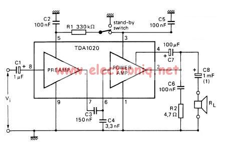
The TDA1020 is a monolithic integrated 12 W audio amplifier housed in a 9-lead single in-line (SIL) plastic package. Although it is designed primarily for car audio applications, it can also be utilized in various other audio applications. The TDA1020...
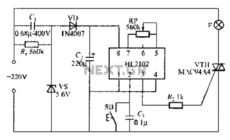
A thirty mining lamp control ASIC production delay lamp circuit is straightforward. It utilizes the HL2102 IC from Wuxi Love Core Microelectronics Co., Ltd. The circuit is designed to control a light with a timed delay, allowing for regular...
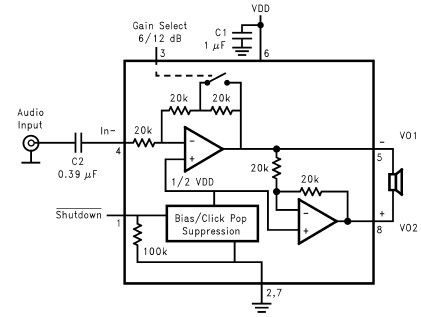
The LM4096 audio amplifier circuit diagram represents a straightforward audio amplifier capable of delivering a maximum output power of 1 watt, utilizing a minimal number of external electronic components. The LM4906, an audio power amplifier, is specifically engineered for...
This circuit provides a visual 9-second delay using 10 LEDs before closing a 12-volt relay. When the reset switch is closed, the 4017 decade counter is reset to the 0 count, illuminating the LED driven from pin 3. The...