
9 Second LED Timer and Relay Circuit

The circuit utilizes a 555 timer configured in astable mode, generating a clock pulse that controls a 4017 decade counter. The 4017 counter has 10 output pins, each corresponding to a count from 0 to 9. The reset switch, when activated, sets the counter back to its initial state, lighting up the LED connected to pin 3, which serves as an indicator that the circuit is ready to begin counting.
The timing capacitor (22uF) plays a crucial role in determining the delay duration. As the capacitor charges through a resistor connected to pins 6 and 2 of the 555 timer, it creates a time delay. The charging process is interrupted when the reset switch is opened, allowing the capacitor to discharge and the timer to generate a 1-second pulse. This pulse is fed into the 4017 counter via pin 14, enabling it to increment its count with each pulse.
The 4017 counter's output pins (0 to 9) are used to drive the 10 LEDs sequentially, providing a visual indication of the countdown. When the counter reaches the 9th count, it triggers pins 11 and 13 to go high, which stops the counting process and activates a relay. This relay can be used to control an external load, such as a motor or another circuit, effectively utilizing the delay mechanism.
For applications requiring a longer delay, modifications can be made by increasing the capacitance of the timing capacitor or the resistance value connected to the 555 timer. This flexibility allows for customization based on specific timing requirements, making the circuit versatile in various electronic applications.This circuit provides a visual 9 second delay using 10 LEDs before closing a 12 volt relay. When the reset switch is closed, the 4017 decade counter will be reset to the 0 count which illuminates the LED driven from pin 3. The 555 timer output at pin 3 will be high and the voltage at pins 6 and 2 of the timer will be a little less than the lower t
rigger point, or about 3 volts. When the switch is opened, the transistor in parallel with the timing capacitor (22uF) is shut off allowing the capacitor to begin charging and the 555 timer circuit to produce an approximate 1 second clock signal to the decade counter. The counter advances on each positive going change at pin 14 and is enabled with pin 13 terminated low.
When the 9th count is reached, pin 11 and 13 will be high, stopping the counter and energizing the relay. Longer delay times can be obtained with a larger capacitor or larger resistor at pins 2 and 6 of the 555 timer.
🔗 External reference
Related Circuits
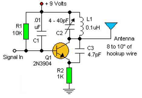
This basic RF oscillator circuit is easy to build and the components are not critical. Most of them can be found in your junk parts box. The L1 antenna coil can be made by close winding 8 to 10...
The RF oscillator using the inverter N2 and 10.7MHz ceramic filter is driving the parallel combination of N4 to N6 through N3. Since these inverters are in parallel, the output impedance will be low so that it can directly...
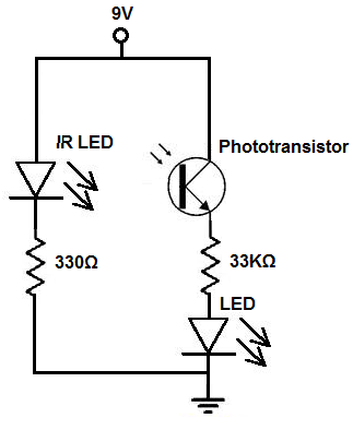
There are two methods to construct a proximity detector. The first method involves mounting the infrared (IR) LED and the phototransistor so that they face each other. In this configuration, the infrared light emitted by the IR LED is...
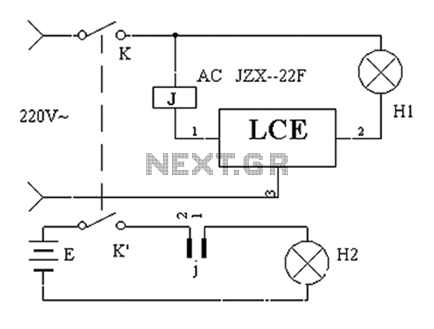
The application circuit operates the device as illustrated below, allowing for intermittent lighting in specific situations (e.g., during surgery). It utilizes an LCE module for blackout emergency lighting, which activates automatically after a power failure, ensuring uninterrupted illumination. In...

This stereo amplifier utilizes the NE5517/A and features an excellent tracking accuracy of 0.3 dB, which is typical. The offset can be adjusted using the potentiometer, Rp. For AC-coupled amplifiers, the potentiometer can be substituted with two 5.1 k...
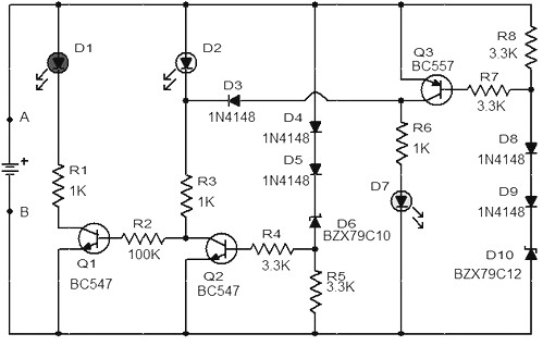
When the battery voltage is 11.5V or lower, transistor Q1 is activated, causing LED D1 to illuminate. If the battery voltage is between 11.5V and 13.5V, transistor Q2 is activated, resulting in LED D2 lighting up. At a battery...