
Basic Oscillator (Tone Generator) At 1.8 KHz -alarm circuits
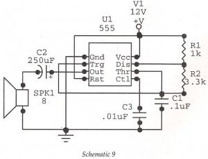
The astable oscillator circuit based on the 555 timer operates in a continuous oscillation mode, generating a square wave output. The frequency of oscillation is determined by the resistors R1 and R2, and the timing capacitor C. The formula for calculating the frequency (f) of the output square wave is given by:
\[ f = \frac{1.44}{(R1 + 2R2) \cdot C} \]
Where:
- R1 is the resistance connected between the discharge pin (Pin 7) and the threshold pin (Pin 6),
- R2 is the resistance connected between the threshold pin (Pin 6) and ground,
- C is the timing capacitor connected between the threshold pin (Pin 6) and ground.
The duty cycle of the output waveform can also be influenced by the values of R1 and R2, allowing for customization of the signal characteristics based on specific application requirements. The output at Pin 3 can be easily interfaced with an 8-ohm speaker, ensuring that the alarm tone is audible.
Capacitor C2 plays a vital role in preventing DC voltage from reaching the speaker, which could potentially damage it. The introduction of a potentiometer in the circuit allows for real-time adjustments to the frequency, providing flexibility in the alarm tone.
For enhanced volume output, a transistor can be integrated into the circuit to serve as an amplifier. The transistor should be configured in a common-emitter configuration to achieve the desired amplification.
Construction considerations include ensuring that all components are securely mounted on the Vero board, with attention to minimizing the lengths of connections to reduce signal degradation. Proper soldering techniques should be applied to ensure reliable electrical connections.
The design is versatile and can be adapted for various applications beyond alarm systems, such as tone generators or signal modulators, making it a valuable addition to an electronics project toolkit.Here we have an astable oscillator built around 555, which gives an alarm tone of 1. 8 KHz directly driving a speaker. This is basic alarm circuit, which is later used in many other projects in the book. While the circuit shows only 1. 8 KHz operation, it can be adapted to different applications by changing frequency and duty cycle after manipulatin g the timing components as per the formula. The circuit is shown in Schematic 9. Resistances Rl, R2, and capacitor C determine the frequency. Changing these values change the frequency. You can also manipulate the tone by changing the capacitor at Pin 5. You can modulate the tone also. Try connecting a 10 K resistor from secondary of the transformer, i. e. , before the rectifier and connect it to Pin 5, the Control terminal. Output will wobble at the mains frequency of 50Hz. Output at Pin 3 is coupled to the speaker of 8 ohms. The capacitor C2 is essential to block DC. You can also vary the frequency by adding a preset potentiometer in the in the timing components. Try changing the timing capacitor also. You can increase the volume by amplifying the output with a transistor. You will find such applications later. Construction is straightforward. Use a small Vero board suitable for ICs. Mount the capacitors and resistances close to the board. C2 is an electrolytic capacitor. IC should be fixed finally and if you have not got the skill of soldering well, use of IC base will be helpful. If you wish to vary the tone, solder 100K variable resistance (preset), between power supply and IK (Rl) and change the tone as you like it.
We aim to transmit more information by carrying articles. Please send us an E-mail to wanghuali@hqew. net within 15 days if we are involved in the problems of article content, copyright or other problems. We will delete it soon. 🔗 External reference
Related Circuits

The CMOS amplifier is biased into the linear region by resistor RB. The pi-type crystal network (C1 and C2, and XTAL) provides the 180-degree phase shift at the resonant frequency, which causes the circuit to oscillate. The described circuit utilizes...
Although labelled as distortion, this is a soft clipping device, using germanium diodes. It's a good example of how little you need for a good basic sound. You could easily swap (or switch) these diodes to silicon types for...
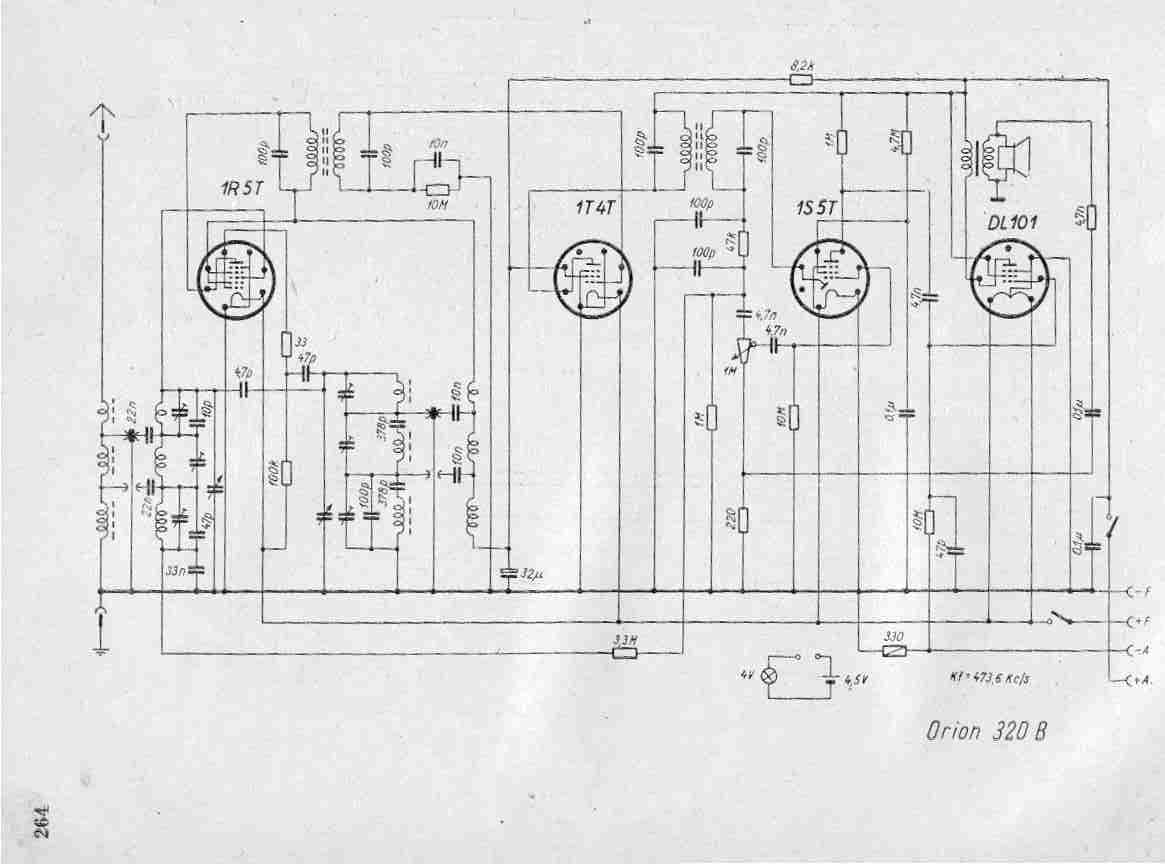
Create a repository of circuits and service data for vintage valve and transistor radios. While many resources are available online, they often come at a cost. The intention is to share circuits and manuals with others rather than profit...
Crystal Y1 generates a fundamental frequency clock signal of 14.31818 MHz. U31 is a Dual Voltage Controlled Oscillator (VCO) that produces a 14.31818 MHz clock signal, referred to as the color clock, at pin 10. The output frequency can...
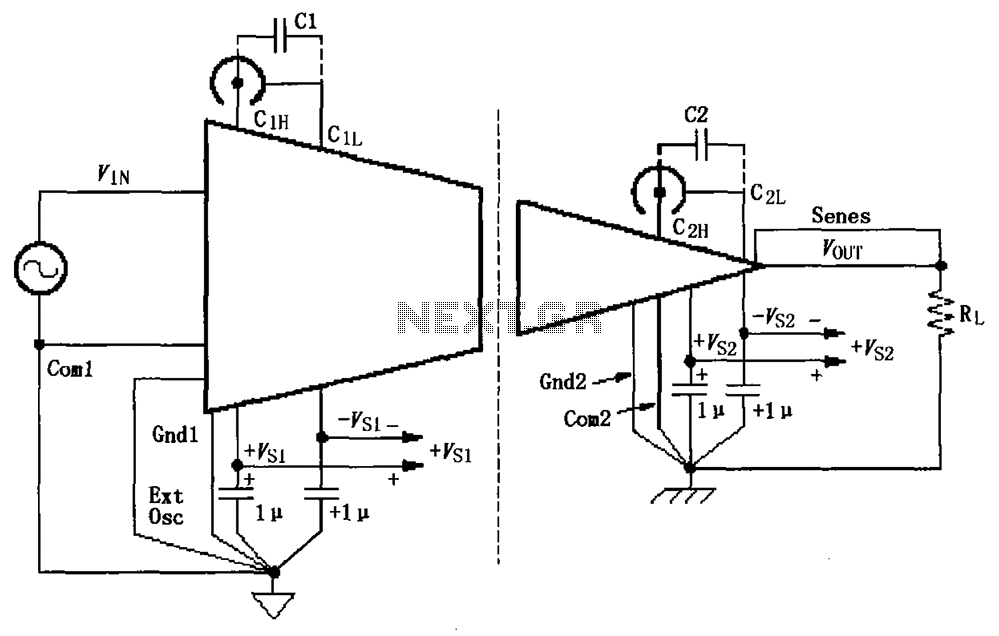
The basic connection circuit for ISO120/121 includes signals and power supply. Each power supply terminal must have a 1 µF tantalum capacitor as a bypass filter, and the printed circuit board layout should allow for the bypass capacitor to...

The circuit utilizes six 12-volt lead-acid batteries to power the load. Three batteries are connected in series to generate 36 volts, while the other three are connected in parallel to maintain 12 volts. The total discharge current is 30...