
DC-Coupled Audio Amplifier Circuit

The audio amplifier circuit described utilizes a DC coupling mechanism, which enhances audio fidelity by providing a direct current path between stages without the need for capacitive coupling. This approach simplifies the design by removing the requirement for a dual power supply, allowing for a more compact and efficient layout. The voltage divider formed by resistors R1a and R1b sets the bias point for the input signal, ensuring that the amplifier operates within its linear range.
The use of integrated circuit IC1 simplifies the amplification process while providing a consistent gain of 11, which is adjustable through potentiometer P1, allowing for user-defined volume control. The feedback network consisting of C2 and R2 is critical for stabilizing the amplifier. C2 not only facilitates the coupling of the audio signal to the virtual earth reference but also introduces a potential for oscillation, which requires careful consideration in the design phase. The choice of R2 is crucial as it dampens any oscillatory tendencies that may arise from the feedback loop created by C2.
In practical applications, the values for C2 and R2 can be optimized through empirical testing to achieve the desired performance characteristics, particularly in terms of output noise levels and response times. The circuit's stability can be monitored using an oscilloscope, revealing the transient response of the virtual earth point during power-up and allowing adjustments to be made to minimize stabilization time.
Overall, this audio amplifier design exemplifies a straightforward yet effective approach to audio amplification, leveraging DC coupling to achieve high fidelity while minimizing complexity and component count.This is a design circuit of audio amplifiers with DC coupling to the load are not often encountered these days, even though they offer definite advantages. One advantage is that there is no need for the complication of a second (symmetric) power supply; another is good frequency and phase response.
Also, no special electrolytic capacitors are need ed for voltage stabilization, and switch-on thump` is much reduced. This is the figure of the circuit; It consists of a voltage divider, a voltage follower and the loudspeaker in the headphones, whose other side is connected to the junction of two electrolytic capacitors, providing the virtual earth. The potential at this point is, of course, half the supply voltage. All we need to do now is suitably couple in the audio signal to be amplified. This figure shows a practical realization of this idea in the form of a stereo headphone amplifier. The amplifier itself consists of IC1 and P1, R3 and R4 (giving a gain of 11). This part of the circuit demands no further explanation, and the same goes for the voltage divider mentioned above, formed by R1a and R1b.
The signal is coupled in via the potentiometers. C2 and R2 have a special purpose: C2 connects the bottom end of the potentiometers (ground for the input signal) to the virtual earth. However, this capacitor creates a feedback path which can lead to oscillation of the amplifier under some circumstances.
R2 damps this tendency to oscillate. It is possible to calculate suitable values for these components, but it is better to determine them by experiment. C2 must be sufficiently large that stray electric fields do not cause unacceptable hum at the output.
R2 must be sufficiently large that the voltage at the amplifier`s virtual earth stabilizes quickly enough after switch-on. The polarity of the electrolytic is unimportant as no significant voltage appears across the network.
It is possible to try the circuit out with the C2/R2 network shorted and observe the behavior of the circuit at switch-on using an oscilloscope. Depending on the degree of asymmetry in the circuit, the voltage at the virtual earth point can take a considerable time to stabilize.
🔗 External reference
Related Circuits
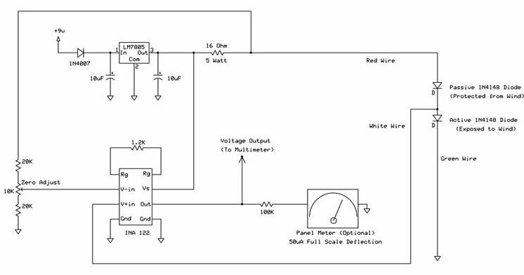
The following circuit illustrates a wind speed indicator circuit. It operates with a constant 5 VDC output provided by the LM7805 voltage regulator, using a 9 VDC supply. The wind speed indicator circuit is designed to measure and display wind...
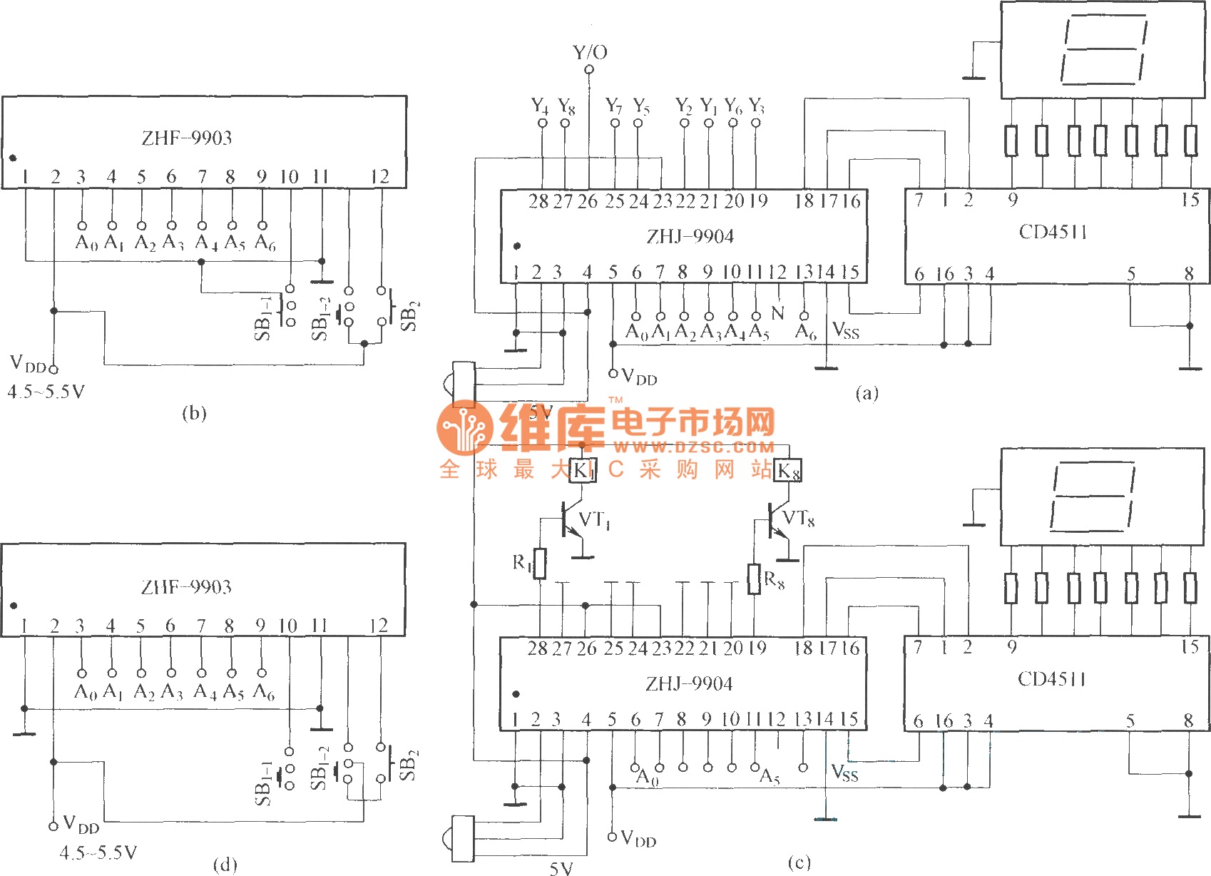
This is an eight-way signal remote control selection circuit composed of ZHJ-9904. It includes a remote control transmitter circuit, an eight-way switch control circuit, and a remote control transmitter. The eight-way signal remote control selection circuit utilizing the ZHJ-9904 is...
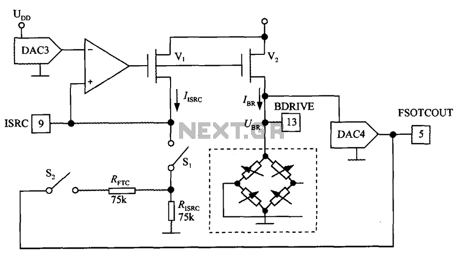
The excitation circuit for the digital pressure signal conditioner MAX1458 is illustrated. The output DAC3 is utilized to adjust the sensor excitation current (IBR), enabling full-scale fine calibration. The reference current (IISRC) is determined by the resistor RISRC and...
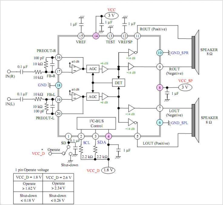
The AN41240A is a single-chip integrated circuit (IC) designed for audio applications. It employs a single-hall-sensor drive on the input side of the spindle motor drive block and utilizes a low-noise direct PWM drive of sine wave on the...
The voltage to be sampled is applied to the input of R2, a 100K linear taper potentiometer, while the other end of R2 is grounded. Consequently, the signal level that is sent to the buffering level shifter U1-A and...
The 4017 traffic light circuit connects four legs to the green LED and two legs to the amber LED. This configuration raises the question of whether it could function with only one leg per LED. Each output is activated...