
Door Chime with ATtiny12
At the end of the 10 hour period, the amber LED goes off and the doorbell is enabled. 24 Hours after the button was last pushed, the amber LED comes back on and the door chime circuit is disabled again. this cycle repeats every 24 hours, and because its timing is set by a crystal oscillator, it should be able to go for months or years without needing to be reset.
The circuit consists of a power supply, a capacitor back-up circuit, a Atmel ATtiny12 microcontroller as a timer, and solid state realy circuit to switch the AC voltage in the doorbell circuit. The simple user interface is comprised of a resync button to synchronize the timer, a bypass switch to bypass the timer if desired, and two status indicator LEDs.
It is designed to be used by people who are not technically inclined. The bell transformer, the doorbell button, and the doorbell are not in the enclosure - they are built into the house. The bypass switch and resync (or reset) button are mounted on the enclosure. Power for the circuit is derived from a half wave rectifier. One end of the bell transformer (the one with the orange wire, marked "ORN" connected to it) connects to circuit common each half cycle through one of the diodes in the diode bridge.
During the same half cycle, the 1N4002 conducts, charging the 330 uf capacitor up to a maximum of 11 volts. The filtered voltage powers the 78L05 5 volt regulator. The current is limited with the 728 Ohm dropping resistor to a maximum of 30 milliamps in order to minimize the maximum load on the bell transformer, and to limit the amount of power that could be dissipated by any component on the board in the event of a component failure.
The use of eight 1/4 watt resistors connected in series makes me feel a little more comfortable than using a single 750 Ohm 2 Watt resistor since the power dissipated will be spread over a large area of the phenolic circuit -pheonlic tends to discolor from heat more easily than fiberglass board, and even if a few of the resistors shorted, the others would be able to handle the increased dissipation -giving a little extra safety. As a rule, I don't use resistors beyond 50% of their rated power. In this case, the resistor string runs at 35% of rated power. A .033 farad (not microfarad) capacitor is connected to the 2SA1020Y and the 2N4401 to provide backup power to keep the timer running in the event of a power failure.
The 2N4401 is there to connect the output of the 5 volt regulator to the ATtiny12 microcontroller when AC voltage is present, and more importantly, to disconnect the controller's power supply from the LEDs when AC voltage is not present. Disconnecting the ATtiny12 from the LEDs keeps the LEDs from discharging the .033 farad capacitor. The 2N4401 is there to turn on the 2SA1020Y when power is first applied to the circuit, then to quickly disconnect itself from the circuit when the +5 volts starts to dip.
The .033 farad capacitor supplies voltage to the ATtiny12 through the 1k resistor. By the way, you can use an 2N2907 in place of the 2SA1020Y. 🔗 External reference
Related Circuits

An 8-ohm speaker functions as both a microphone and an output device. The BC109C transistor operates in common base mode, providing substantial voltage gain while ensuring a low impedance input suitable for the speaker. Self DC biasing is implemented...
This circuit provides a delayed visual indication when a doorbell switch is pressed. Additionally, a double pole double throw (DPDT) switch can be activated from within the house to light a lamp at the doorbell switch. The lamp can...
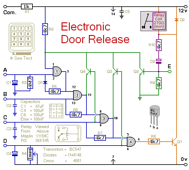
This circuit is designed to operate an electrical door-release mechanism, but it can be utilized for various other applications. Users can enter a four-digit code of their choice, after which the relay will energize for a duration determined by...
The primary components of this doorbell circuit include two NE555 timer integrated circuits (ICs). When the switch S1 is pressed momentarily, the loudspeaker emits a bell tone for the duration determined by the time period of the monostable multivibrator...

Have you ever accidentally left your front door ajar and had a pet escape? This circuit offers a smart solution to this problem. It is relatively simple yet serves as an excellent example. The circuit designed to prevent pets from...
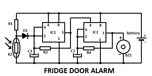
This fridge door alarm operates using a 3V battery supply and should be placed in a small box inside the fridge, near the lamp or close to the opening. The fridge door alarm circuit is designed to alert users...