
Fridge Door Alarm Circuit
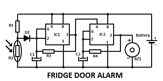
The fridge door alarm circuit is designed to alert users when the refrigerator door is left open for an extended period. The core components of the circuit typically include a microcontroller or a simple logic circuit, a battery power supply, a sensor (often a magnetic reed switch or a tilt sensor), and an audible alarm (such as a piezo buzzer).
The microcontroller or logic circuit is powered by a 3V battery, which is housed in a compact enclosure. This enclosure should be insulated to prevent moisture ingress, ensuring the longevity and reliability of the circuit. The sensor is strategically placed near the door, where it can detect the position of the door when it is closed. When the door opens, the sensor triggers the microcontroller, which initiates the alarm sequence.
The alarm system can be designed to emit a sound after a predefined delay to prevent false alarms from brief openings. The delay can be adjusted based on user preference. The audible alarm is typically a piezoelectric buzzer that produces a loud sound to alert users in case the door is left ajar.
For optimal performance, the circuit can include a low-power sleep mode to conserve battery life when the fridge door is closed. Additionally, a visual indicator, such as an LED, may be incorporated to provide a visual cue when the door is open, enhancing user awareness.
Overall, the fridge door alarm circuit is a practical solution for preventing food spoilage and energy waste, ensuring that the refrigerator operates efficiently.This fridge door alarm is using a 3V battery supply should be placed (in a small box) in the fridge near the lamp or close to the opening. With the door cl.. 🔗 External reference
Related Circuits

The ramp voltage from the low-frequency oscillator IC1 modulates IC2, thereby producing a rising and falling tone similar to the wail of police cars. The described circuit utilizes a low-frequency oscillator (IC1) to generate a ramp voltage. This ramp voltage...

The electric valve control circuit consists of three main parts: the main lines, control lines, and power consumption brake line. The main circuit includes a power switch (QF), three-phase AC contactors (KM1, KM2), a thermal relay (FR), and a...
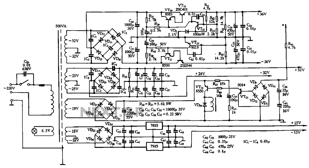
The power supply circuits for servo systems are critical during both the adoption and operational stages. The power supply circuit for servo systems is designed to provide stable and adequate voltage and current levels necessary for the servo motors to...
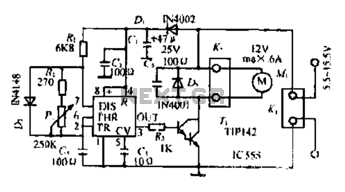
Most governors utilize pulse width modulation (PWM) and pulse position modulation (PPM) in their circuits. The 555 timer is commonly used in these applications. The pulse width is typically fixed at 0.5 milliseconds, which is essential for the functioning...
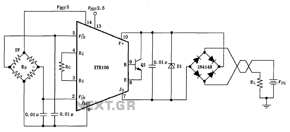
The circuit utilizes a Zener diode D1 to limit surge voltage and incorporates a four-diode rectifier bridge to prevent reverse voltage. The Zener diode D1 is rated at 36V, with optional choices being 1N4753A or 6KE39A. When the loop...

When switches SW1, SW2, or SW3 are open, the input sensitivity is optimized for high-output devices such as CD players, tuners, tape recorders, iPods, miniDisc players, and computer audio outputs. The 750 Ohm value for resistors R3, R13, and...