
Door Light Switch

The automatic door light switch circuit operates using a simple yet effective mechanism. It typically incorporates a magnetic reed switch or a similar sensor that responds to the door's movement. When the door is opened, the sensor is triggered, allowing current to flow through the circuit and illuminating the connected lamp. Conversely, once the door is closed, the sensor returns to its original state, interrupting the current flow and turning off the lamp.
The circuit often includes a relay to handle the lamp's load, as well as a power supply unit that provides the necessary voltage and current. A resistor may be included to limit the current flowing through the sensor, ensuring its longevity and reliability. Additionally, a diode may be placed in parallel with the relay coil to prevent back EMF when the relay is de-energized, protecting other components from voltage spikes.
This type of circuit is beneficial for enhancing convenience and safety in various settings, such as homes, offices, and public buildings, by ensuring that areas are well-lit when accessed. Proper design considerations, such as component ratings and power supply specifications, are crucial for the circuit's effective and safe operation.This automatic door light switch circuit turns ON a lamp when a door is opened then turns it OFF when the door is opened again. The working principle of th.. 🔗 External reference
Related Circuits
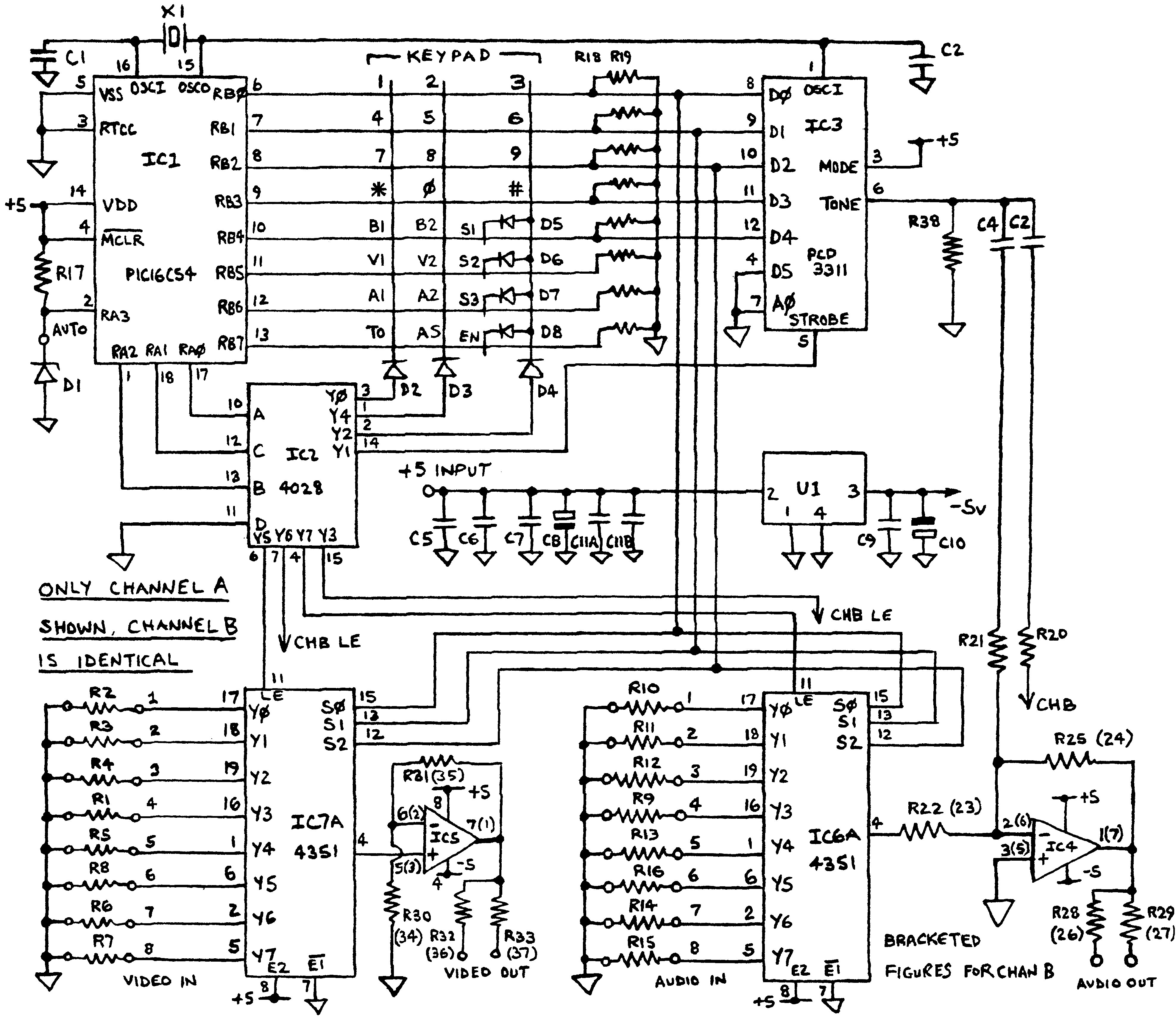
Before applying power, check for shorts on the board. This design operates from a 5V supply; connecting it directly to a 12V supply will certainly damage it. The current draw is minimal, approximately 70mA, so if using a 12V...
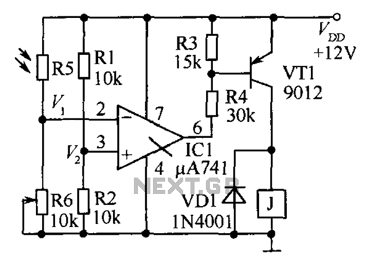
The circuit functions as a precision bright light control circuit, operating independently of power supply voltage and ambient temperature. Resistors R1, R2, R6, and the photosensitive resistor R5 form a two-arm Wheatstone bridge. The precision bright light control circuit utilizes...
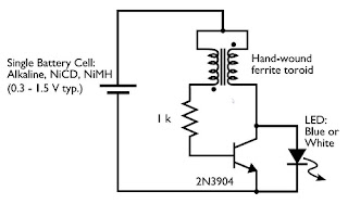
Tired of experimenting with capacitors? It's time to explore supercapacitors, which offer significant storage capabilities. This article provides instructions on building a small LED flashlight utilizing supercapacitors. A minimum voltage of 2 volts is necessary to illuminate the LED,...
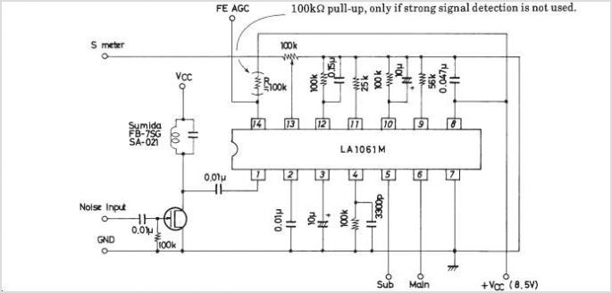
The LA1070 is an automatic gain control integrated circuit designed for use with automotive on-glass antennas. It is produced by Sanyo Semiconductor Corporation. The LA1070 operates by automatically adjusting the gain of the antenna signal to maintain a consistent output...
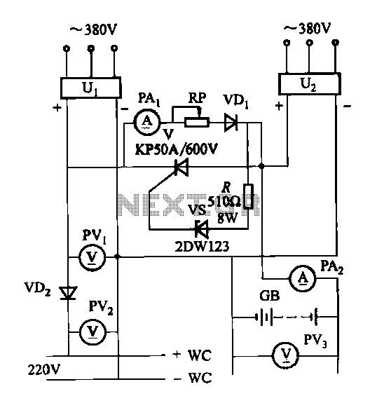
The DC panel battery is commonly utilized in power plants and substations within DC systems. To enhance the safety and reliability of the current system, an uninterrupted power supply switching circuit may be implemented. This circuit includes components such...
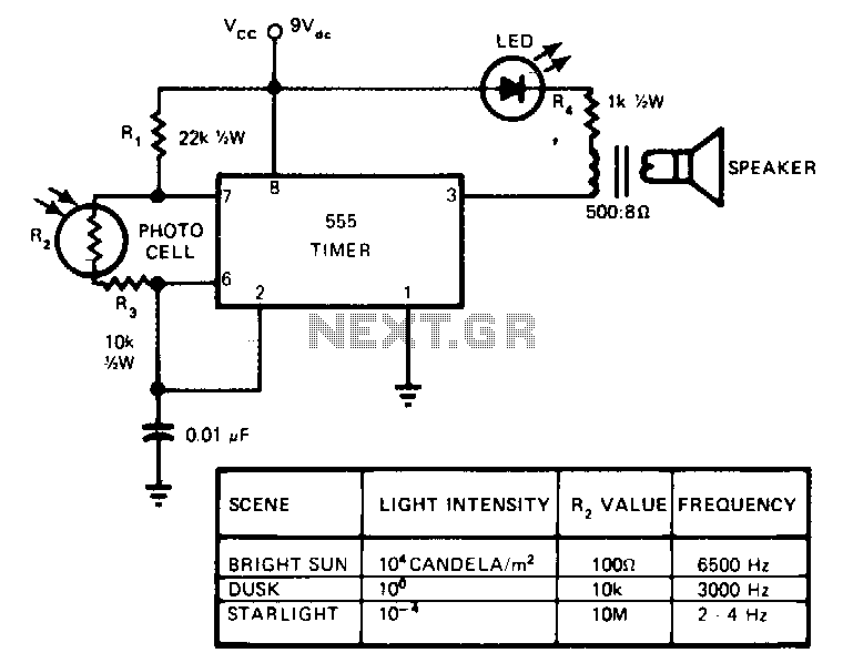
This circuit's frequency of oscillation increases directly with light intensity. The greater the light intensity, the higher the frequency of the oscillator. The 555 timer operates in the astable oscillator mode where frequency and duty cycle are controlled by...