
LED Flashlight Use Super capacitor Schematic Diagram

To construct the LED flashlight circuit with supercapacitors, the following components and steps are essential:
1. **Components Required**:
- Supercapacitor (rated for at least 2 volts)
- LED (appropriate for the desired brightness)
- Toroidal inductor (from an energy-saving lamp)
- Transistor (compatible with the inductor)
- Zener diode (to regulate voltage)
- USB port (for power input)
- Resistors (for current limiting)
- Diode (to ensure current flows in one direction)
2. **Circuit Design**:
- The supercapacitor will serve as the main power source, charging up to the required voltage. The LED will be connected in series with the toroidal inductor and transistor to form a Joule Thief circuit. This configuration helps to boost the voltage from the supercapacitor to a level sufficient to light the LED.
- The LED acts as a diode, allowing current to flow only in one direction, thereby maintaining the necessary voltage across it for illumination.
- The toroidal inductor and transistor work together to oscillate the current, enabling the supercapacitor to discharge efficiently and power the LED until depletion.
3. **Safety Precautions**:
- When extracting components from energy-saving lamps, care must be taken to avoid damaging the lamp and releasing hazardous materials such as mercury vapor. Proper safety gear, such as gloves and goggles, should be used.
- Ensure that the USB port is not overloaded with power. The supercapacitor has a limited voltage tolerance, so a zener diode is crucial for protecting it from voltage spikes. The zener diode should be selected based on the maximum voltage rating of the supercapacitor to ensure safe operation.
4. **Final Assembly**:
- After assembling the circuit, it should be tested with a multimeter to ensure proper voltage levels before connecting the LED. This will help confirm that the circuit is functioning correctly and that the supercapacitor is charging and discharging as intended.
This project not only illustrates the practical application of supercapacitors but also enhances understanding of energy-efficient circuit designs and component integration.Bored of playing around with capacitors Then its time for you to move on to super-capacitors. These have huge storage capabilities. In this article you will find out how to build a small LED flashlight using supercapacitors. The main disadvantage of capacitors is their large voltage drop. For this project, a minimum voltage of 2 volts is required to light the LED. As a result, the Joule Thief design would be incorporated here. Using this, a AA battery can be used to light an LED till it is completely discharged. In this case, a supercapacitor would be taking the place of the battery. Here an LED is used to perform the function of a diode. This ensures that there is sufficient voltage across the LED. The torus and the transistor used here comes from an energy-saving lamp HS. Care should be taken while removing this from the lamp as a breakage could result in the release of the mercury vapors. A lamp load along with a USB port is added to the circuit. This makes it compatible with a PC or a car radio. A few precautions have to be taken while constructing the circuit. The USB port should not be provided with excess power. The capacitor does not withstand a high voltage and hence a zener diode is connected in parallel to handle the high voltage.
The diode protects the capacitor when the voltage exceeds a certain value. You are reading the Circuits of LED Flashlight Use Supercapacitor And this circuit permalink url it is 🔗 External reference
Related Circuits
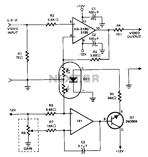
This amplifier utilizes a cascaded operational amplifier (op amp) integrator and a transistor buffer, Q1, to drive the gain control element. With a minor modification, the HA-5190/5195 stage is configured as a conventional non-inverting op amp and includes input...
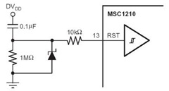
A flash memory schematic can be created using various reset sources, including power-on reset, external reset, software reset, watchdog timer reset, and brownout reset. The accompanying figure illustrates a recommended external reset circuit for the MSC1210, which includes a...
The LED flasher circuits below operate on a single 1.5 volt battery. The circuit on the upper right uses the popular LM3909 LED flasher IC and requires only a timing capacitor and LED. The top left circuit, designed by...

This document provides a circuit diagram for the DOD Overdrive 250 preamp. The DOD Overdrive 250 is similar to the MXR Distortion Plus and several other devices, utilizing a 741 operational amplifier with two diodes on the output channel....
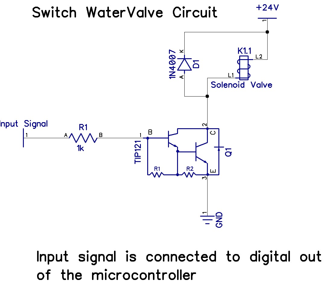
The Arduino Uno has adequate memory and ports, but efficient programming is necessary to store settings in memory. The Mega version offers increased memory and ports. The Shako valve operates on 24 volts DC; however, 12 volts is preferred...

A real-time controller is a device designed to continuously manage household devices, both in real-time and according to a predetermined schedule. This article focuses on a series of real-time controllers utilizing the AT89C2051 microcontroller, which serves this purpose effectively....