
door loock circuit
1. Begin by testing the lock solenoids. Disconnect the lock module and connect the solenoids directly to a battery at the connector plug. Each solenoid consists of two coils, one for locking and one for unlocking. With the large connector detached, hot-wire each coil to the breaker to verify functionality; audible feedback from the solenoids indicates proper operation. If any solenoid is defective, replacements cost approximately $110 each, but they can be repaired by rewinding for about $10 worth of wire, requiring around 70 feet of #20 enameled motor wire sourced from an electric motor repair shop. It is also essential to ensure that the breaker is operational.
2. Open the existing lock module to check for stuck relays, which can typically be unstuck manually. The module is not sealed; simply remove the tie-wrap to access the internals.
3. Purchase two 81-89 Chrysler Starter Relays (Gen Automotive #32870) at around $12 each, along with assorted colors of #12 stranded wire and several crimp connectors. Additionally, acquire two 1N1007 diodes from a local electronics store for approximately $0.59. These relays should be wired in series with the existing lock module, allowing the module to control only the relays, while the starter relays supply power to the solenoids. This configuration significantly reduces power consumption, as solenoids draw less current than starters, enhancing their longevity. The relays can be mounted adjacent to the existing lock module, but they must be opened to remove the internal diode and solder the 1N1007 diode across the appropriate connections. The installation requires three solder connections, with the remainder being crimp-on terminals for easy reversibility.
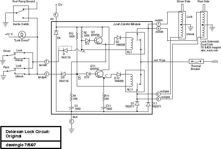
The operational theory indicates that when the lock module is activated, point B is not grounded through D5, leading to a pull-up through R12. This activates Q11, charging C11 through R11 and raising point C to approximately 11 volts. Upon switching to the 'unlock' position, point B is grounded via a diode, while point C remains charged at around 10 volts. This voltage discharges through the relay coil and R11, keeping the relay engaged until the charge diminishes, at which point the relay returns to its default state. The transition between the upper and lower circuits prepares the system for subsequent locking operations after a brief recharge period for C1. The relay's operation is influenced by the capacitor, which explains the absence of protection diodes in normal conditions; however, fluctuations in the system, such as faulty door switches, could potentially damage the diode-capacitor pair. To mitigate this risk, the inclusion of transient voltage suppressors (Transzorbs) is recommended, as they can effectively manage voltage spikes by dissipating energy rapidly and recovering afterwards.This is a great contribution to the ongoing study of the lock control module, including instructions and photos of how to upgrade the module to reduce its standby current consumption for increased battery life. Assumes that you are slightly competent with electronics. Large (400k) downloadable PDF file. I worked up something on my locks to fix the problem with the stock logic box. You might have a good time with this and save a bunch of money. Everything I mention here adds up to about $35. 1. Test the lock solenoids by unplugging the lock module and hot-wiring them to battery at the connector plug. Each solenoid has two coils, one for lock and one for unlock. With the large connector unhooked, you can hot-wire each coil in turn to the breaker and see if the solenoids make noise in the doors.
You probably have one or more burned out. These can be replaced for $110 apiece, or you can take them apart and rewind them for about $10 worth of wire. These must work before you do anything else, or you`ll just fry everything. Each solenoid coil takes about 70 feet of #20 enameled motor wire. Get from an electric motor repair place. Also make sure that the breaker is good. 2. Open up the existing lock module and make sure the relays aren`t stuck. If they are you can usually just unstick them. The module is not sealed, just slide the tie-wrap off the end and it opens. 3. Go to Trak and buy two 81-89 Chrysler Starter Relays, Gen Automotive #32870, about $12 ea. Also get some assorted colors of #12 stranded wire and a bunch of crimp connectors. You`ll also need two 1N1007 diodes from Radio Shack for about 59 cents. These relays get wired in series with the existing lock module. This means the lock module is now only controlling the relays, and the starter relays are feeding the solenoids.
The solenoids are much less drain than a starter so they should last forever. The can be mounted next to the existing lock module. You have to open them up, clip out the diode inside and solder the 1N1007 diode across the appropriate connections. I have this all done on my car and it works great. You need to make three solder connections, everything else is crimp-on terminals and is easily reversible.
Here`s a nice theory of operation submitted by Martin Gutkowski. This will help if you are electronically inclined. He also submitted the corrected drawing. One of these days I`ll fix the original, but since I converted from a Mac to a PC I`ve lost the artwork. -dave Meanwhile, point B is _not_ grounded through D5, so is pulled up through R12. This has switched on Q11 to charge up C11 through R11, so point C is now at 11 ish volts. Now I change to the `unlock` position. I have now grounded (via a diode) point B, but point C is still 10 ish volts due to C11 being still charged up, so it discharges through the relay coil and R11 causing the relay to be on.
After a short time, this charge runs out, and the relay returns to it`s normal position. The lower and upper circuits have now exchanged states and the upper circuit is ready to lock again (after a little time for C1 to recharge). Due to the relay being switched by the capacitor, you can see why some knob at Lucas thought protection diodes were unnecessary since under normal operation, there can be NO BACK EMF from the relay.
almost clever. unless. you waggle your key in the lock or your door switches are dodgy/dirty, in which case, you might fry your diode/cap pair as you could loose your ground before the cap has discharged which may (only may, mind you, depending largely on the inductance in the relay, I think) cause point B (A) to shoot above the rail. A pair of 13 ish volt Transzorbs would do the trick here (unusual for me to recommend traszorbs, I know!
- Transzorb is a trademark I think. basically, it is a fast avalanche diode that can dissipate large amounts of energy for a very short period of time and recover. Used to stop spiky voltag 🔗 External reference
Related Circuits

The circuit connection is illustrated in figures a and b. In figure a, a star-shaped winding is used with shunt capacitance, while figure b depicts a triangular winding with capacitance connected in parallel. The working capacitance (Cc) is calculated...
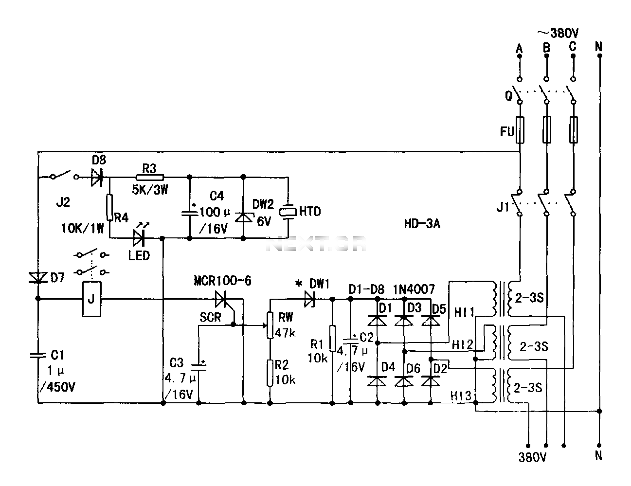
A current transformer H11-3 needs to be constructed. Select a transformer core with a minimum power rating of 2W for the first secondary winding. Use enameled wire with a diameter of 0.12 mm and wind approximately 1000 turns. The...
The TDA2822 is a low-power stereo operational amplifier commonly utilized in Walkman devices and headphones. It is capable of delivering an output power of 250 milliwatts. This operational amplifier is particularly suitable for low-volume production applications and serves as...
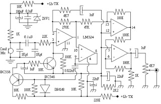
This circuit can be utilized in intercom systems, walkie-talkies, low-power transmitters, and packet radio receivers. Transistors T1 and T2 constitute the microphone preamplifier. Resistor R1 provides the necessary bias for the condenser microphone, while preset VR1 serves as a...
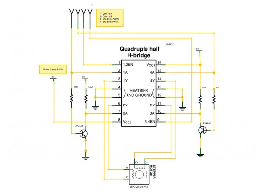
A stepper motor controller based on schematics available on the Arduino website. Initially, a two-pin configuration was attempted for a bipolar stepper motor, but it did not function as expected, especially with the library provided on the site. The...
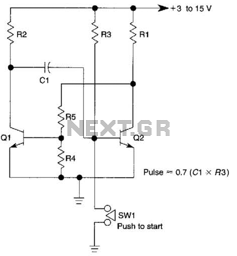
This circuit is activated when switch SW1 is pressed, grounding the base of transistor Q2. The pulse rate is approximately equal to 0.7 multiplied by the product of resistor R3 and capacitor C1. The described circuit features a transistor Q2,...