
Three-phase squirrel cage motor running single phase connection circuit

The circuit design incorporates two distinct winding configurations: star and triangular. The star-shaped winding in figure a is beneficial for applications requiring higher voltage and lower current, as it allows for a more balanced load distribution across the phases. The shunt capacitance associated with this configuration helps in power factor correction, improving the overall efficiency of the system by minimizing reactive power.
In contrast, the triangular winding shown in figure b is advantageous for applications that demand higher current capabilities. The parallel connection of capacitance in this configuration serves to enhance the system's ability to handle reactive loads, thereby stabilizing voltage levels and improving performance under varying load conditions.
The working capacitance (Cc) is a critical parameter in both configurations, as it directly influences the performance of the circuit. The formula provided for calculating capacitance takes into account the rated current, voltage, and the power factor, which is essential for determining the effective capacitance required for optimal circuit operation. Understanding the interplay between these variables allows for precise tuning of the circuit to meet specific operational requirements, ensuring reliability and efficiency in power delivery.
In summary, the circuit connection described utilizes both star and triangular winding configurations, each with its respective capacitance arrangements, to enhance performance and efficiency in electrical systems. The calculation of working capacitance is essential for optimizing the circuit's functionality, ensuring that it operates effectively within its designed parameters. Circuit connection as shown in a, b, in which a star-shaped FIG winding shunt capacitance of the connection, Fig. B triangular winding capacitance in parallel connection. FIG W orking capacitance cc capacity is calculated by the following formula: C 19501Ucos µ. Where C is the capacitance of the work ( F); I is the rated current (A); U single-phase rated voltage (v); cos µ into work rate factor.
Related Circuits
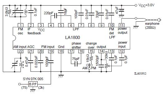
This portable AM/FM radio circuit is designed using the LA1800 integrated circuit (IC) along with several external components. The circuit diagram illustrates that the LA1800, manufactured by Sanyo Semiconductors, requires only a few additional components. The output signal is...
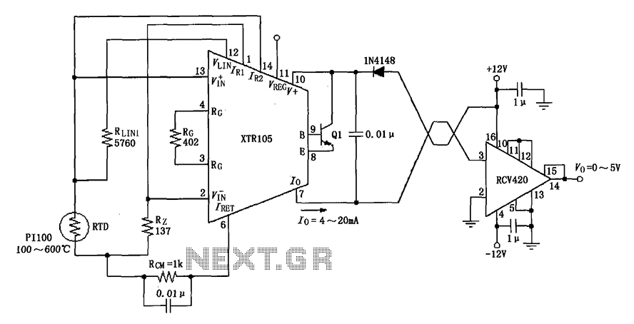
The circuit utilizes a Pt100 type resistance temperature detector (RTD). It operates within a temperature range of 100 to 600 °C, where the XTR105 outputs a current of 4 to 20 mA, and the RCV420 provides an output voltage...
A high-quality and straightforward intercom circuit utilizing only three transistors. By pressing switch S2, the circuit generates ringing signals. To create a two-way intercom, two identical circuits can be constructed and combined as illustrated in diagram 2. The circuit's...
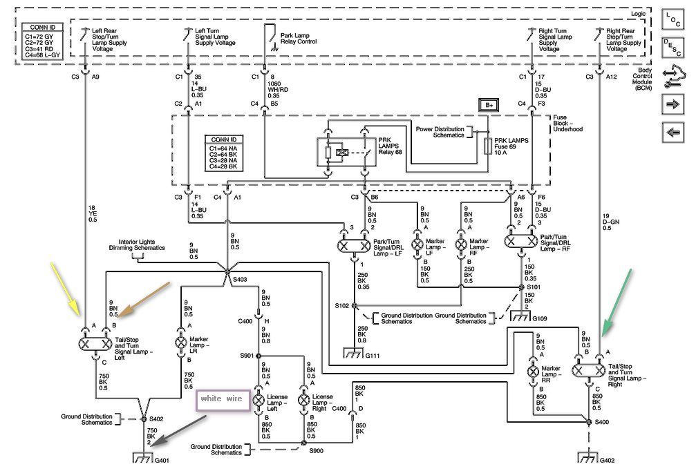
The left side of the vehicle operates correctly, with the running lights and brake light functioning properly. However, the turn signal is not working when wired directly into the harness. There is a preference to avoid purchasing a plug-in...
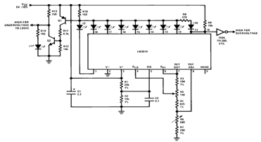
By utilizing several resistors, LEDs, and the LM3914 bar/dot display driver IC, it is possible to create a straightforward 5V voltmeter monitor circuit. This circuit offers TTL-compatible undervoltage and overvoltage warning signals. A complete circuit schematic is available below. The...
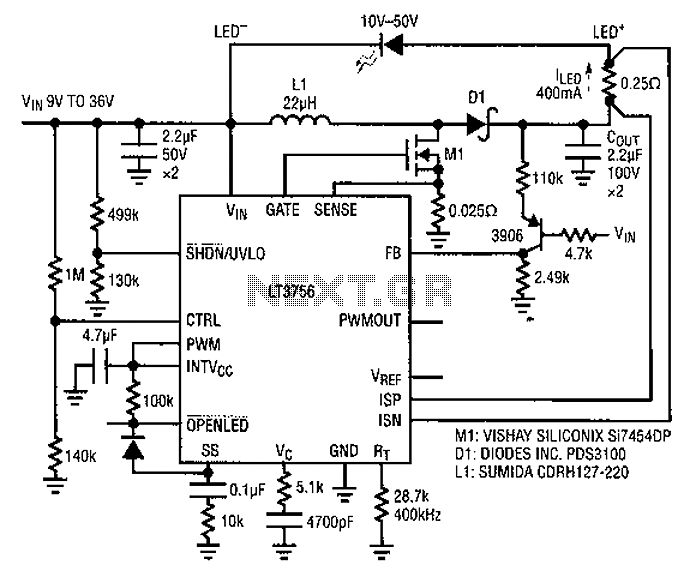
Common LED driver requirements include a wide and overlapping range of LED string voltages and input voltages. Many designers prefer to use an LED driver circuit that accommodates various battery power sources and multiple LED strings. This universal configuration...