
DoorBell Bird Voice Electro Suite
The Doorbell Bird Voice Electro Suite is an innovative electronic circuit designed to enhance the traditional doorbell experience by integrating a bird voice sound module. This circuit typically consists of a microcontroller, sound playback module, push button switch, and a power supply unit.
The microcontroller serves as the central processing unit, responsible for interpreting the button presses and controlling the sound playback. When the push button is pressed, the microcontroller activates the sound module, which then plays a pre-recorded bird voice sound. This adds a unique auditory element to the doorbell, distinguishing it from conventional systems.
The sound playback module may utilize a digital audio chip capable of storing and reproducing audio files. It is important to select a module with sufficient memory to accommodate high-quality audio samples. The module is connected to a small speaker, which should be appropriately rated for the power output of the circuit to ensure clear sound reproduction.
The power supply unit can be derived from the existing doorbell wiring or a separate low-voltage power adapter, depending on the design requirements. It is essential to include voltage regulation components to ensure the microcontroller and sound module operate within their specified voltage ranges.
In addition to the basic functionality, enhancements can be made by integrating features such as adjustable volume control, multiple sound options, or even wireless connectivity for remote activation. These additional features can increase the versatility and user-friendliness of the Doorbell Bird Voice Electro Suite.
Overall, this electronic circuit represents a modern approach to doorbell design, combining functionality with an engaging user experience through sound.This is DoorBell Bird Voice Electro Suite, to replace the old doorbell, to give the freshness in using the excitement new doorbell.. 🔗 External reference
Related Circuits
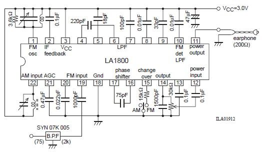
This portable AM/FM radio circuit is designed using the LA1800 integrated circuit (IC) along with several external components. The circuit diagram illustrates that the LA1800, manufactured by Sanyo Semiconductors, requires only a few additional components. The output signal is...
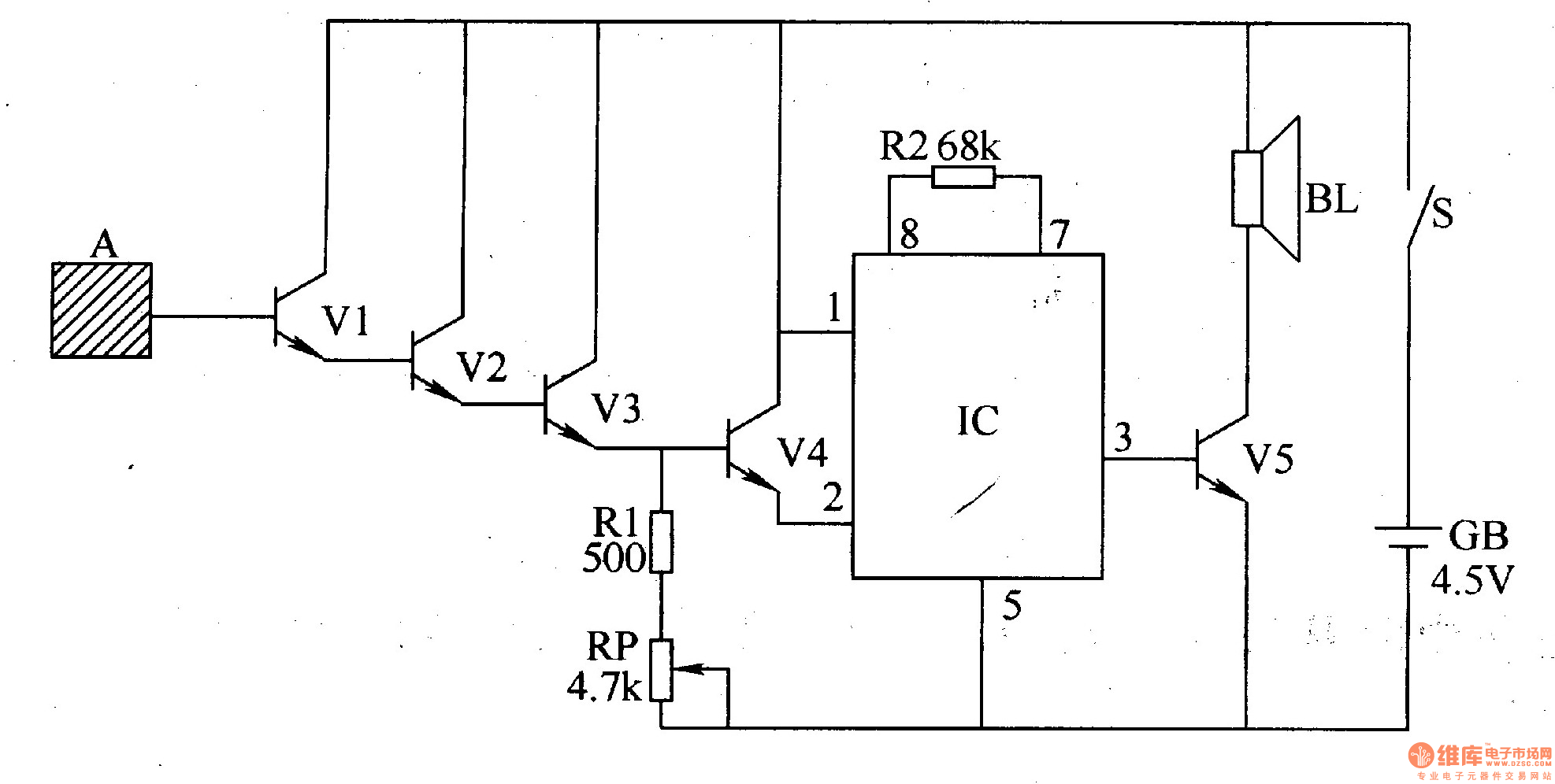
The inductive electronic doorbell circuit consists of an inductive electronic switch and a music generator circuit, as illustrated in Figure 3-115. The inductive electronic switch circuit includes an inductive electrode A, transistors V1-V4, a resistor R1, and a potentiometer...
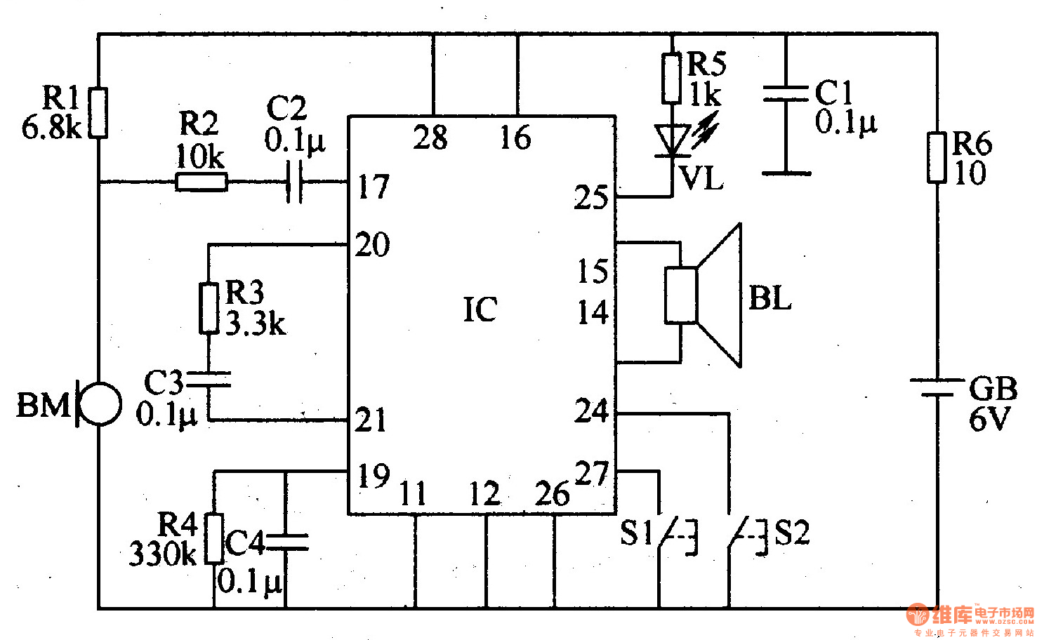
The recordable electronic doorbell consists of a recording and playback integrated circuit (IC), resistors R1-R6, capacitors C1-C4, a microphone (BM), a speaker (BL), control buttons S1 and S2, a battery (GB), and an LED (VL). Resistors R1-R5 should be...
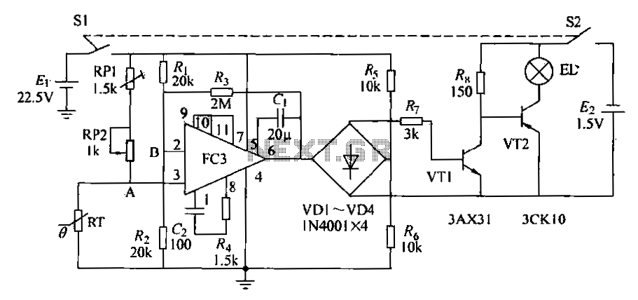
The circuit diagram illustrates an electronic thermometer. RT represents the thermistor, while A denotes an integrated operational amplifier. The diodes VD1 to VD4 provide a unidirectional output signal. The transistors VT1 and VT2 form a switching circuit. When the...
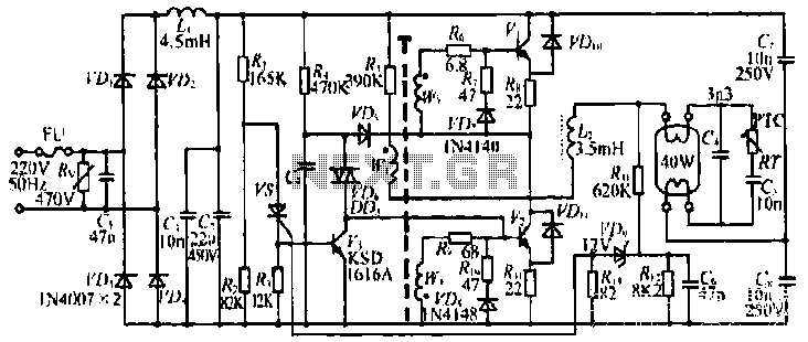
The figure illustrates the input from the varistor, which serves an overvoltage protection role. Components VDi and VD4 function as rectifiers, while L1 and C2 are utilized for filtering. The circuit comprises R, C9, and VD6, which are part...
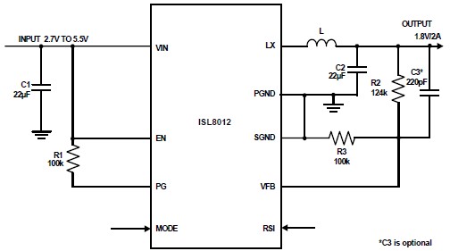
The ISL8012 is a high-efficiency, monolithic, synchronous step-down DC-DC converter that can be designed into a simple electronic project. It supports a maximum continuous output current of up to 2A from an input supply range of 2.7V to 5.5V....
Warning: include(partials/cookie-banner.php): Failed to open stream: Permission denied in /var/www/html/nextgr/view-circuit.php on line 713
Warning: include(): Failed opening 'partials/cookie-banner.php' for inclusion (include_path='.:/usr/share/php') in /var/www/html/nextgr/view-circuit.php on line 713