
40W fluorescent lamp electronic ballast circuit
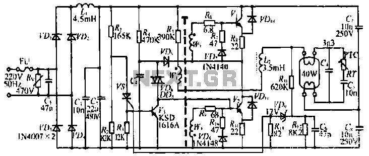
The circuit design presented is a sophisticated arrangement that integrates multiple components to ensure reliable operation and protection of the lamp system. The use of a varistor for overvoltage protection is critical, as it prevents damage to sensitive components during voltage spikes. The rectifiers (VDi and VD4) convert AC to DC, while the filtering components (L1 and C2) smooth the output to provide a stable voltage for subsequent stages.
The oscillation starting circuit, comprising resistors and capacitors (R, C9, and VD6), is essential for initiating the high-frequency oscillation necessary for lamp ignition. The transformer (T and H) plays a dual role, providing coupling and stepping up the voltage to the required levels for lamp operation.
The inclusion of a PTC thermistor as a preheating element is a notable feature, as it enhances the reliability of lamp ignition by gradually increasing the filament temperature. This gradual increase helps to prevent thermal shock to the lamp, extending its lifespan.
The protective circuit is designed to respond to abnormal conditions, such as lamp failure or aging. By monitoring voltage levels and employing a zener diode, the circuit can detect when the lamp is not functioning correctly and take appropriate action to prevent damage. The SCR's rapid response to trigger voltage changes ensures that the circuit can quickly enter a safe state, minimizing the risk of component failure.
Overall, this circuit exemplifies a well-engineered solution for lamp control, combining functionality with safety features to ensure long-term reliability and performance.The figure shows that input from the varistor overvoltage protection role. VDi - VD4 rectifier, L1, C2, q filtering. R, c9 and VD6 composition oscillation starting circuit, the transformer T and H, V and other components transformer coupling high-frequency oscillation circuit. Choke Island, C4 and C7 etc. LC series resonant circuit. Among them, the island is the series resonant inductor, but it is also chokes. PTC thermistor element preheating the lamp cathodes. RN, RI2, vdG, Ru, vs code composed of the protective circuit and the like. L. Can increase the rectifier diode conduction angle of the rectifier bridge input terminal of AC current tends to be continuous, power factor increased to 055 by the close 08. After the power is turned on, the entire flow filter output DC voltage of H {c9 start capacitor is charged through the resistor R4.
When the voltage across the c9 reached about when 32V, diac vIX avalanche conduction, switching power supply base for the pole tube injection current, K is turned on first. By coupling Ts,, V2 turns conducting, high-frequency high voltage is applied across the lamp output. The capacity of the island above the C4 capacity, and by the TPTC thermistor resistance at room temperature only 200n left and right, so after power flows through the filament current is not 0, only by PTC and G.
Filament current flowing through the PTC to raise its temperature, resistance increases. After about 1 second, reaches the Curie point temperature, the resistance value of 10M n above, filament preheat current through C4, immediately aroused k, C4 and other series circuit of a resonance in the start capacitor C4 high voltage is generated across the lamp start ignite. Once the win lamp burning, the island only play a limiting role. The protective circuit is: Once the lamp and the lamp can not start aging, etc., between L2 and the filament is bound to appear high EMF, the Rt., R12 partial pressure, sufficient to zener diode VDg breakdown.
SCR vs Having obtained the trigger voltage is turned on, so that V3 from off jump into saturated conduction state, the collector potential is only about 0.2V, forcing Vz off, the oscillation circuit stop Jt oscillation, the realization of ballast protection function. Only troubleshooting, reconnect the power to light the lamp.
Related Circuits
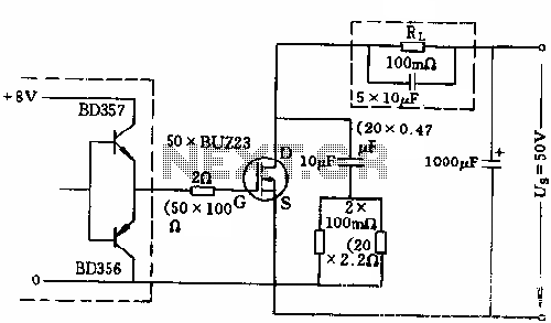
The circuit employs 50 BUZ23 field effect transistors (FETs) arranged in parallel, with a tube blocking voltage of 100V. The control power required is minimal, eliminating the risks associated with second breakdown and the positive temperature coefficient phenomenon in...
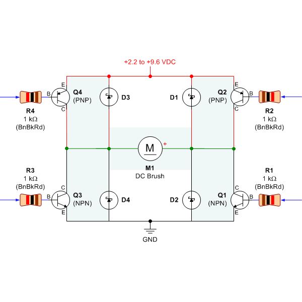
Selecting the appropriate DC motor is essential for constructing mobile robots. Testing DC motors is straightforward and can be accomplished by assembling a basic DC motor circuit. The components needed for this circuit include a DC motor, a battery...
There are several situations where a power failure can be particularly challenging to manage, especially in the bathroom. This compact circuit is designed to be cost-effective, particularly beneficial during a shower. The backup lamp remains off as long as...

The project described in this article is a constant Q, fully expandable graphic equaliser. Where most "conventional" graphic EQ circuits have a Q that is dependent on the setting of the pot, this one maintains the same Q at...
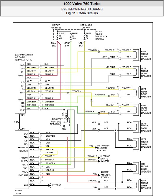
The following document contains the system wiring diagram of the radio circuit for the Volvo 760 Turbo 1990. Please note that this is a system wiring diagram, not a schematic diagram. Download the radio circuit system wiring for the...
For several years, a rear fog lamp has been mandatory for trailers and caravans to enhance visibility in foggy conditions. When the fog lamp is activated, the fog lamp of the towing vehicle must be turned off to prevent...
Warning: include(partials/cookie-banner.php): Failed to open stream: Permission denied in /var/www/html/nextgr/view-circuit.php on line 713
Warning: include(): Failed opening 'partials/cookie-banner.php' for inclusion (include_path='.:/usr/share/php') in /var/www/html/nextgr/view-circuit.php on line 713