
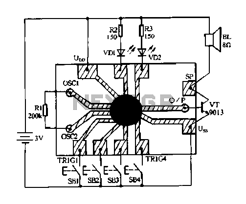
Doorbell Circuit with Diagram and Schematic using UM 66 IC

The doorbell circuit utilizes the UM66 integrated circuit, known for its capability to generate musical tones. The circuit typically includes a power supply, a push-button switch, the UM66 IC, and an output device such as a speaker or buzzer.
The power supply provides the necessary voltage and current to the circuit, often sourced from a standard battery or an AC power adapter, depending on the design requirements. The push-button switch serves as the user interface, allowing the user to activate the doorbell. When the button is pressed, it triggers the UM66 IC to begin playing a pre-programmed melody.
The UM66 IC is connected to the output device, which converts the electrical signals generated by the IC into audible sound. The choice of speaker or buzzer will influence the sound quality and volume of the doorbell. Additionally, a resistor may be included in the circuit to limit the current flowing through the speaker or buzzer, protecting the components from damage.
This circuit can be enhanced with additional features such as an LED indicator that lights up when the doorbell is activated, or a capacitor for smoothing the power supply to minimize noise. Overall, the simplicity of the design makes it accessible for hobbyists and beginners in electronics, while still providing a functional and pleasant doorbell solution.A simple doorbell circuit diagram and schematic designed using UM 66 IC, which is a music sound generator. This is an easy to make electronic doorbell circuit.. 🔗 External reference
Related Circuits
The heart of the PWM Fan Controller is a PIC 12F675 microcontroller. This microcontroller is reading the analog output of a LM35 temperature sensor using a ADC (analog to digital converter). The resulting digital value is converted to a...

The circuit can incorporate a buffer gate at the input to ensure compatibility with TTL or other logic levels. This design is intended for a TTL 0V circuit to accommodate a 3.5V input signal swing. Additionally, it generates a...
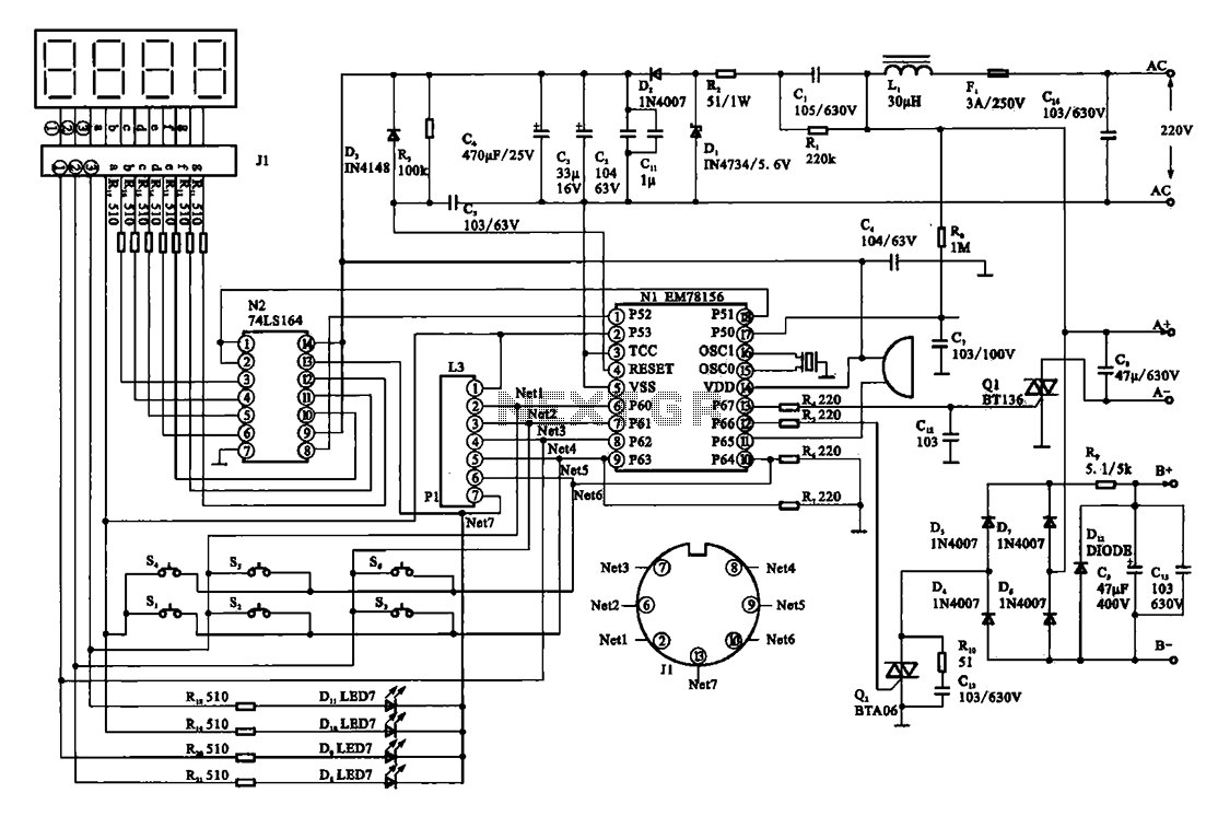
The display circuit is utilized in a typical digital massager. At the heart of the control circuit is the microprocessor EM78156, which receives manual operation instructions. It triggers two transistors to supply voltage to the DC motor (A +,...

This circuit is a conventional Pierce type oscillator that utilizes a JFET. It employs fundamental mode crystals and demonstrates decent performance and reliability. The Pierce oscillator is a popular configuration for generating stable oscillations, particularly in applications requiring a stable...
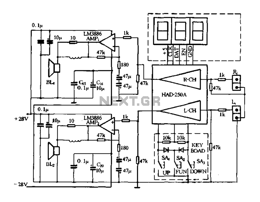
Figure 4-20 illustrates the HAD250A-3 active speakers and amplifier circuit, which features the LM3886 integrated amplifier. This circuit operates with a 25V power supply and delivers an output power of up to 50W per channel, making it suitable for...
Constantly changing light and sound analog controller circuit 04 The circuit designated as the "Constantly Changing Light and Sound Analog Controller Circuit 04" is designed to modulate both light and sound outputs in a dynamic manner. This type of...
Warning: include(partials/cookie-banner.php): Failed to open stream: Permission denied in /var/www/html/nextgr/view-circuit.php on line 713
Warning: include(): Failed opening 'partials/cookie-banner.php' for inclusion (include_path='.:/usr/share/php') in /var/www/html/nextgr/view-circuit.php on line 713