
Massage digital display circuit
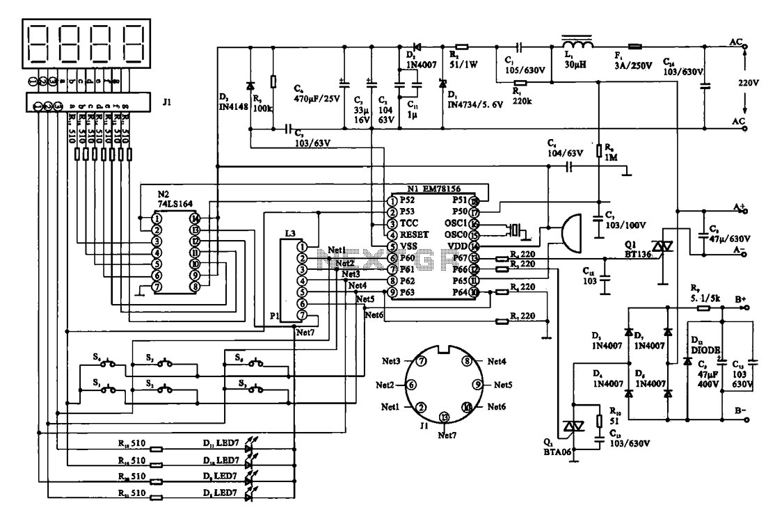
The display circuit in a digital massager operates by integrating a microprocessor, specifically the EM78156, which serves as the central control unit. This microprocessor is responsible for interpreting user inputs and executing control commands for the device's various functions. The manual operation instructions are processed by the EM78156, which activates two transistors that control the power supplied to the DC motor. The motor is essential for the massager's operation, providing the necessary mechanical movement.
The power supply to the motor is divided into two sets of terminals: A +, A- for one motor direction, and B +, B- for the opposite direction. This dual control allows for bidirectional movement, enhancing the massaging capability of the device. The transistors act as electronic switches, enabling or disabling the motor supply voltage based on the processed instructions from the microprocessor.
Additionally, the circuit incorporates an 8-bit register, denoted as N2, which plays a crucial role in driving the digital display. This register holds the data that corresponds to the operational status and settings of the massager, allowing for dynamic visual feedback to the user. The digital display presents various information, such as speed settings, massage modes, or operational timers, thereby improving user interaction and experience.
Overall, the integration of the EM78156 microprocessor, the transistor-driven motor control, and the 8-bit register for the display forms a cohesive and efficient electronic circuit that enhances the functionality of a digital massager.Display circuit as shown in a typical digital massager. The core of the control circuit is a microprocessor EM78156, it then received instructions manual operation of the circu it, on the one hand by triggering the two transistors to provide a DC motor supply voltage (A +, A- and B +, B-), with displacement through 8 bit register N2 digital display drive circuit.
Related Circuits
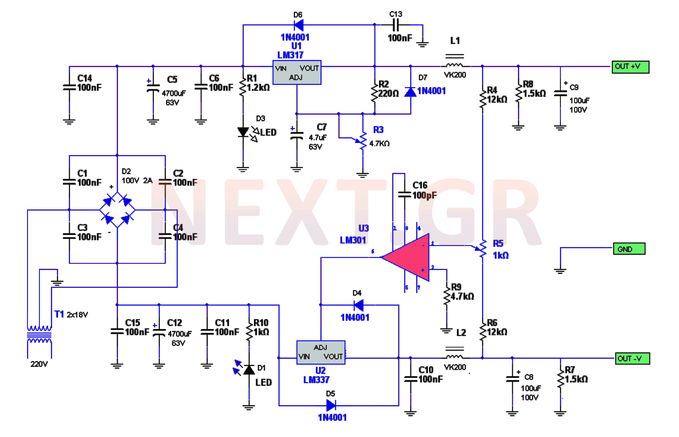
The power supply circuitry includes a 220/2 * 18V / 3.5A transformer, a rectifier, a smoothing filter, a power amplifier (LM301), and two regulators (LM317 and LM337). The voltage from the transformer is rectified by a bridge rectifier. Capacitors...
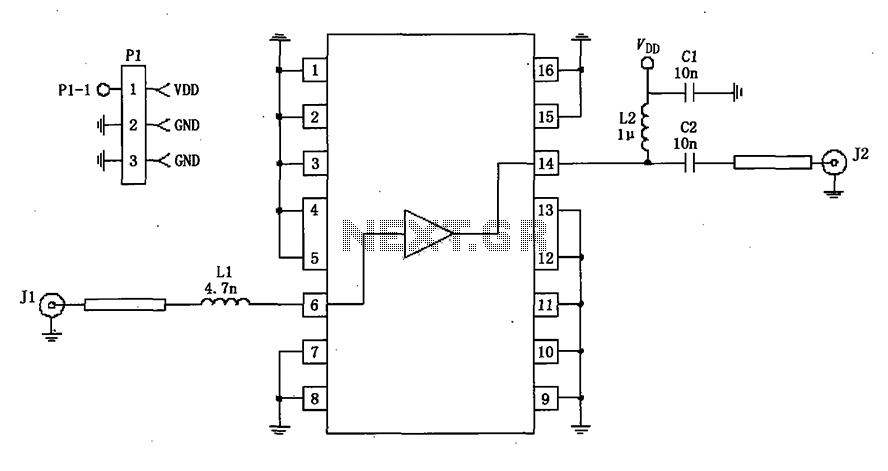
A 50-ohm impedance is illustrated in the RF2320 linear amplifier circuit, which is configured for input and output using transmission lines and inductive or capacitive components to create a matching network. The RF2320 linear amplifier circuit is designed to operate...
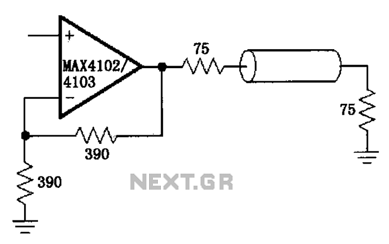
The MAX4102/4103 serves as a video configuration and RF distribution amplifier. The signal input for the MAX4102/4103 undergoes amplification before being output. To minimize the reflection during the transfer process, it is essential to select a termination impedance that...
This circuit is designed to provide alerts after a predetermined time interval. It is ideal for tabletop games that necessitate a fixed duration for answering questions or moving pieces. In this context, it serves as a contemporary alternative to...
This circuit is a simple air flow detector that signals the presence of air flow. The sensor utilized is a filament incandescent lamp. Components include an air flow detector, a sensor, an LED, and an LM339 operational amplifier. The air...
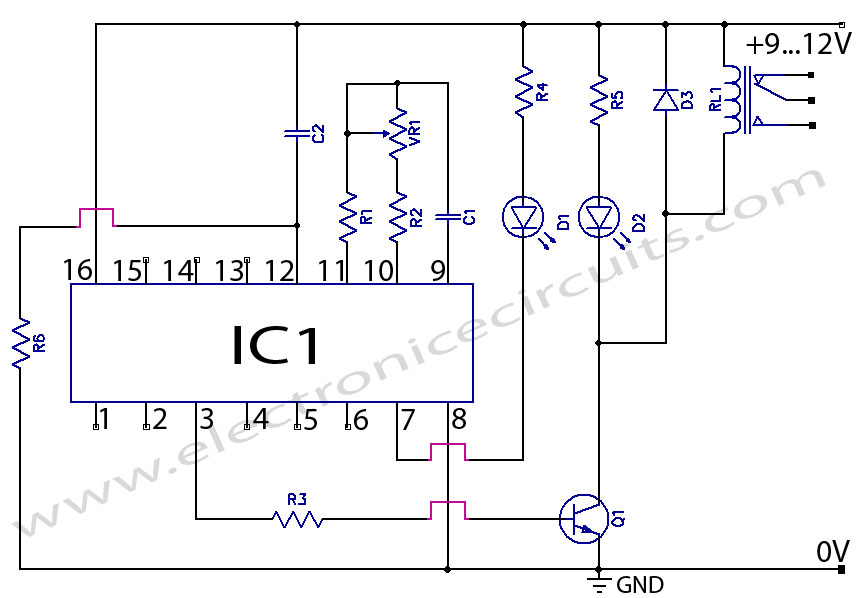
CD4060 Timer Circuit 1 minute to 2 hours This is a 1 minute to two-hour timer switch. The 14-stage binary ripple counter Type 4060, IC1, has an... The CD4060 timer circuit is designed to function as a timer switch with...