
Doorbell light for the Deaf
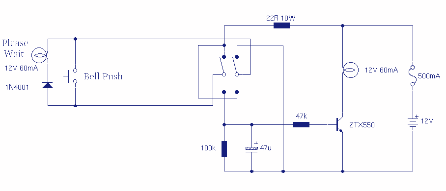
The described circuit functions as a visual aid for doorbell activation, enhancing accessibility for individuals with mobility challenges. The core components include a doorbell switch (S1), a 1N4001 diode, and a 12V 60mA bulb. The circuit is designed to be powered by a standard 12V DC power supply, which is commonly used in doorbell systems.
When the doorbell switch (S1) is pressed, current flows through the switch, triggering the circuit. The 1N4001 diode serves a critical role by preventing reverse current flow, thereby protecting the circuit from potential damage caused by incorrect polarity. This diode ensures that the current flows in one direction, allowing the bulb to illuminate when the doorbell is activated.
The optional 12V 60mA bulb is connected in parallel with the doorbell switch. This configuration allows the bulb to light up simultaneously with the doorbell activation. The illumination of the bulb provides a visual indication for those who may not hear the doorbell ring, particularly useful for individuals who may have hearing impairments or are slow to respond. The phrase "Please Wait" can be illuminated on the lamp, offering a clear message to visitors that assistance will be provided shortly.
In addition, the circuit incorporates a Double Pole Double Throw (DPDT) switch, which allows for control of the lamp from within the house. This switch can be used to turn the lamp on or off independently of the doorbell activation, providing flexibility in its use. The wiring for this circuit can be accomplished using standard two-wire doorbell cable or loudspeaker wire, making it accessible for installation in typical residential settings.
Overall, this circuit design not only enhances the functionality of a standard doorbell but also significantly improves the user experience for individuals with mobility issues, ensuring they are not left waiting unacknowledged at the door.This circuit provides a delayed visual indication when a door bell switch is pressed. In addition, a DPDT switch can be moved from within the house which will light a lamp in the door bell switch. The lamp can illuminate the words "Please Wait" for anyone with walking difficulties. The circuit uses standard 2 wire doorbell cable or loudspeaker wire. In parallel with the doorbell switch, S1, is a 1N4001 diode and a 12 volt 60mA bulb. The bulb is optional, it may be useful for anyone who is slow to answer the door, all you need to do 🔗 External reference
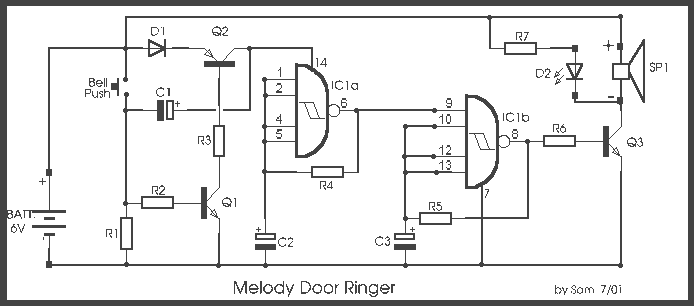
Related Circuits
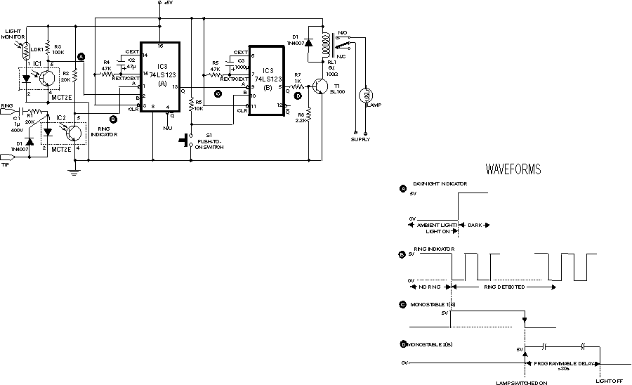
The circuit shown here is used to switch on a lamp when the telephone rings, if the ambient light is insufficient. The circuit uses only two ICs and it can be implemented very easily. A light dependent resistance (LDR),...
In all the houses exist the bells in the door. All want, they have the possibility of being possible to change the intensity, the tone of sound. With this circuit we have this possibility. With the materials round the...

The circuit utilizes the SH803 flash IC, which can store eight different programs and offers various dimming options and light speed adjustments. A button is provided to trigger the control terminal SB on the 9-pin connector for program selection,...
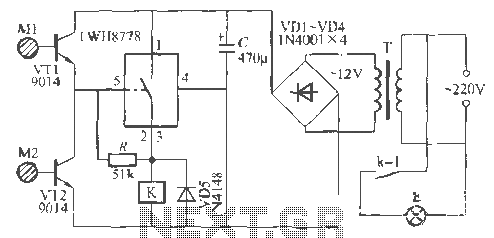
The Rw A77S power system utilizes an integrated circuit fabrication design featuring a dual touch light switch. It employs a transformer (T) for power conversion, a rectifier (VD4), and a capacitor (C) for filtering, resulting in a 12V DC...

A simple doorbell circuit diagram and schematic designed using the UM66 IC, which is a music sound generator. This is an easy-to-make electronic doorbell circuit. The doorbell circuit utilizes the UM66 integrated circuit, known for its capability to generate musical...
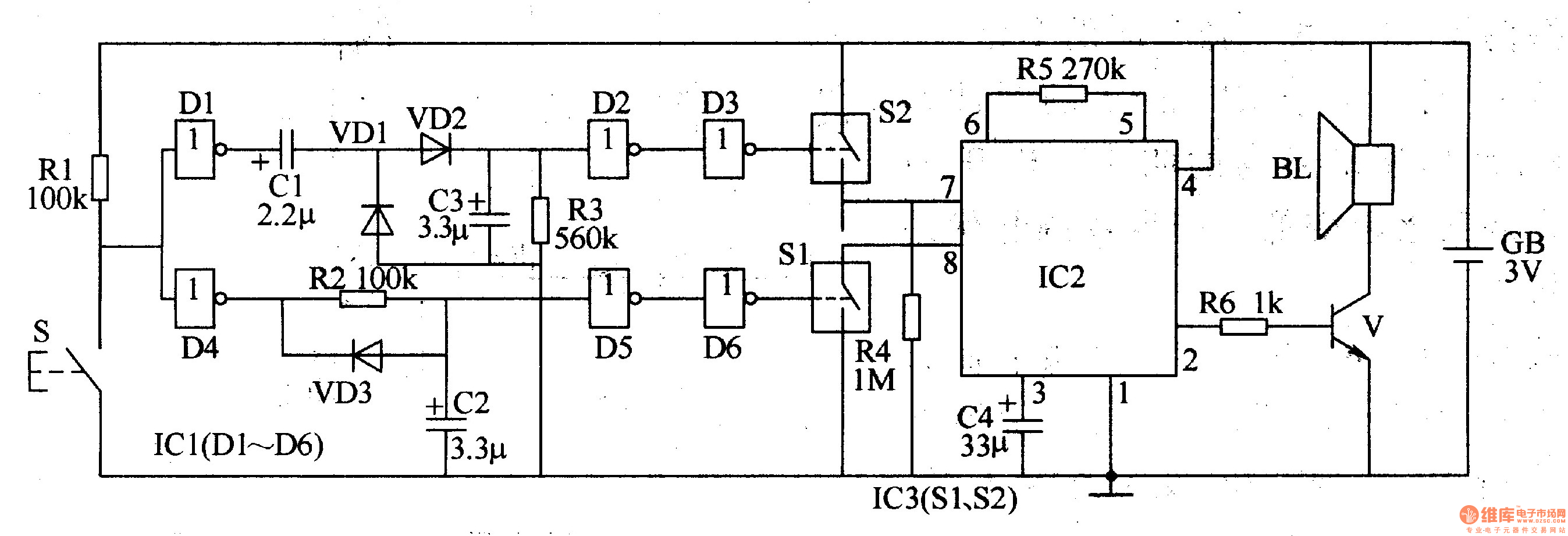
The two-tone electronic doorbell circuit comprises a trigger control circuit and a doorbell generating circuit, as illustrated in Figure 3-108. The trigger control circuit includes a doorbell button (S), resistors (R1-R3), electrical components (C1-C3), diodes (VD1-VD3), six NOT gate...